
Automatic assembling system for steel wire thread insert

A technology for wire screw inserts and automatic assembly, which is applied in metal processing, metal processing equipment, manufacturing tools, etc., can solve the problems of low assembly efficiency, inability to realize automatic assembly, and high labor costs, so as to improve assembly efficiency, reduce labor costs, and reduce labor costs. The effect of reducing labor intensity

Inactive Publication Date: 2021-03-12
上海微波技术研究所(中国电子科技集团公司第五十研究所)
View PDF13 Cites 1 Cited by
  • Summary
  • Abstract
  • Description
  • Claims
  • Application Information

AI Technical Summary

Problems solved by technology

[0006] Patent document CN104369146A discloses an assembly assembly for quickly installing a wire threaded sleeve, including: a centering positioning guide sleeve, the centering positioning guide sleeve is axially penetrated to form a guide channel; and a clamping rotation rod, the clamping rotation The front end of the rod is provided with a clamping groove for clamping the installation handle of the wire screw sleeve; when assembling, the front end of the guide channel of the centering positioning guide sleeve is aligned with the mounting thread hole of the workpiece, and the rear end of the clamping rotating rod is connected with the air trigger. After connecting, insert the rear end of the guide channel of the centering and positioning guide sleeve into the guide channel and go straight through the guide channel while clamping the wire screw sleeve placed in the guide channel and then pass through the front end of the guide channel However, the wire thread sleeve is pressed into the mounting threaded hole of the workpiece, but this design still cannot realize automatic assembly for the entire installation process of the wire thread sleeve, resulting in low assembly efficiency and high labor costs

Method used


Image

  • Automatic assembling system for steel wire thread insert

Examples


Embodiment 1

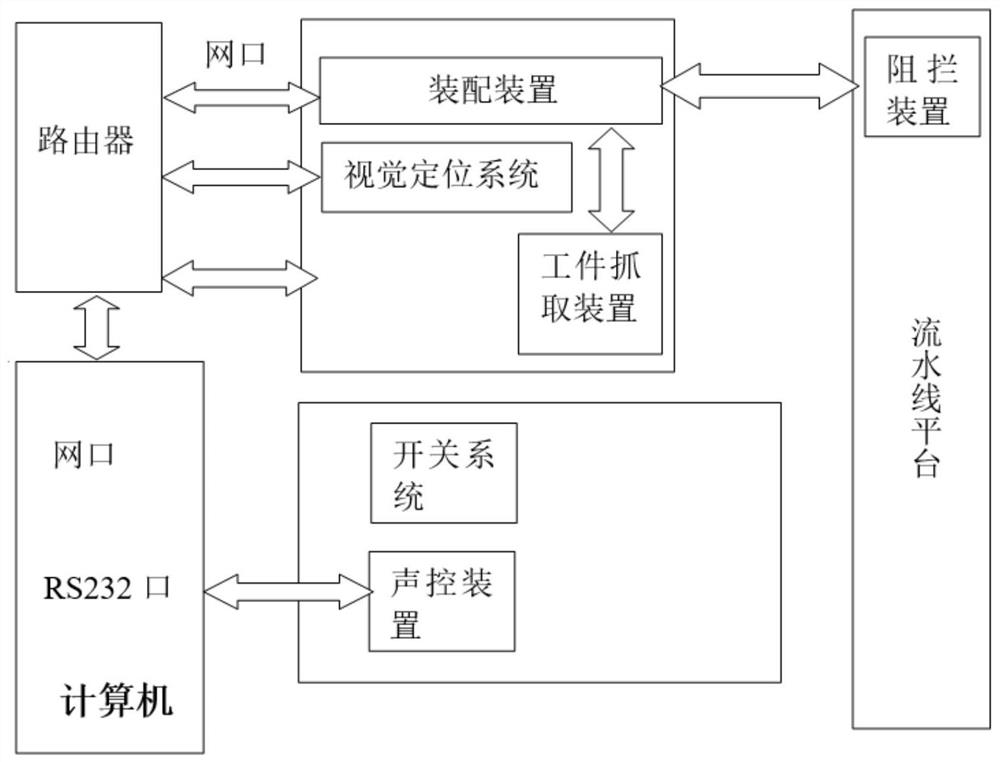
[0038] The present invention provides an automatic assembly system for wire threaded sleeves, including an assembly device, an assembly line platform, a blocking device, a workpiece grabbing device, and a control device. The wire threaded sleeves in the present invention are also called wire sleeves, screw sleeves, and thread expansion sleeves. specifically:

[0039] The assembly device is used for grasping the workpiece to be assembled on the assembly platform, positioning the screw hole of the workpiece to be assembled and assembling the wire thread sleeve in the screw hole of the workpiece to be assembled.

[0040] Specifically, the assembly device adopts a four-axis mechanical transmission device, the four axes on the four-axis mechanical transmission device can be rotated at any angle, and the repeat positioning accuracy of the four-axis mechanical transmission device can reach ±0.02 mm, The four-axis mechanical transmission device can be programmed and controlled, and ha...

Embodiment 2

[0047] Embodiment 2 is a variation example of embodiment 1, specifically as follows:

[0048] The invention provides an automatic assembly system for wire threaded sleeves, which includes an assembly device, an assembly line platform, a blocking device, a workpiece grabbing device, a visual positioning system and a control device, the control device adopts a computer, and the workpiece grabbing device adopts a fixed effect combination The structure of the cylinder oil cylinder, when the workpiece to be assembled is grabbed from the assembly line platform to the assembly platform, the workpiece grabbing device will fix the workpiece to be assembled to the installation position on the assembly platform through the fixing pin, and then pass the two cylinders. The assembly workpiece is pressed tightly to ensure the stability of the workpiece to be assembled, and it is convenient to install the wire screw sleeve.

[0049] The control device is also provided with a voice control sys...

Embodiment 3

[0053] Embodiment 3 is a preferred example of embodiment 1:

[0054] The invention provides an automatic assembly system for wire thread inserts, which includes an assembly device, an assembly line platform, a blocking device, a workpiece grabbing device, and a control device. The assembly device includes an intelligent screwdriver, a special batch head for wire thread inserts, and a pressing device. When it is necessary to assemble the wire thread insert, the special bit for the wire thread insert grabs the wire thread insert and moves the wire thread insert to the position of the screw hole of the workpiece to be assembled, and the pressing device pushes the wire thread insert Press on the screw hole of the workpiece to be assembled and complete the assembly of the wire screw sleeve by the intelligent screwdriver. The torque of the intelligent screwdriver can reach up to 30-160mN.m, the torque accuracy is ±5%, and the detection accuracy is greater than Or equal to 0.01r.

...


PUM


Abstract

The invention provides an automatic assembling system for a steel wire thread insert. The system comprises an assembling device, an assembly line platform, a blocking device, a workpiece grabbing device and a control device, and the assembling device is used for grabbing a to-be-assembled workpiece on an assembly platform, positioning a screw hole of the to-be-assembled workpiece and assembling the steel wire thread insert in the screw hole of the to-be-assembled workpiece; the assembly line platform is used for conveying the to-be-assembled workpiece and an assembled workpiece, and the blocking device is in signal connection with the assembly line platform, detects a workpiece carrying part of the assembly line platform and blocks the workpiece carrying part to a preset position; and theworkpiece grabbing device is used for grabbing the to-be-assembled workpiece on the assembly line platform to the assembly platform and moving the assembled workpiece on the assembly platform to the assembly line platform, and the control device controls the assembly device, the assembly line platform, the blocking device and the workpiece grabbing device to act. According to the system, the assembling efficiency is improved, the labor cost is reduced, automatic assembly is achieved, and the labor intensity of staff is reduced.

Description

technical field [0001] The invention relates to the field of industrial production and assembly, in particular to an automatic assembly system for wire thread inserts. Background technique [0002] The assembly of wire thread inserts is an important basic setting for modern industry, especially in the fields of military and civilian products such as aviation, aerospace, shipbuilding, machinery, and electronics. It is not strong and the installation efficiency is not high, which obviously limits the ability of mass production. [0003] The structural parts of military communication equipment require light weight and good vibration and shock resistance. Therefore, the box body of the product is mainly made of aluminum alloy, and the strength of the threaded hole in the box body is improved by using a wire screw sleeve. The installation of wire threaded sleeves accounts for about 30% of the entire assembly workload. At present, it is mainly completed by manual assembly, and th...

Claims


Application Information

Patent Timeline
Patent Type & Authority Applications(China)
IPC IPC(8): B23P19/00B23P19/027
CPCB23P19/001B23P19/027
Inventor 何盛飞毛建勇杜涛卢尧张立峰张小波丁晓兵王文伟姚双童付维振
Owner 上海微波技术研究所(中国电子科技集团公司第五十研究所)
Learn More