Numerical control machine tool edge folding mechanism for metal plate machining

A technology for CNC machine tools and metal sheets, applied in metal processing equipment, manufacturing tools, feeding devices, etc., can solve the problems of reducing work efficiency, wasting time, unable to automatically adjust the folding position, etc., to improve the folding efficiency and folding. good edge effect

Pending Publication Date: 2021-03-12
江苏云佳金属制品有限公司
View PDF15 Cites 0 Cited by
  • Summary
  • Abstract
  • Description
  • Claims
  • Application Information

AI Technical Summary

Problems solved by technology

[0004] In view of the above situation, in order to overcome the defects of the prior art, the present invention provides a numerically controlled machine tool hemming mechanism for sheet metal processing, which effectively solves the poor hemming effect of most current hemming devices and the inability to Automatically adjust the folding position, waste time and reduce work efficiency

Method used


Image

  • Numerical control machine tool edge folding mechanism for metal plate machining
  • Numerical control machine tool edge folding mechanism for metal plate machining
  • Numerical control machine tool edge folding mechanism for metal plate machining

Examples


Embodiment 1

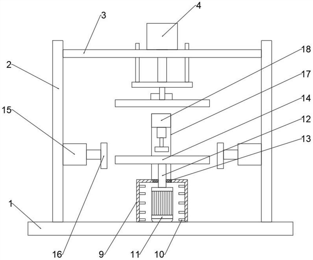
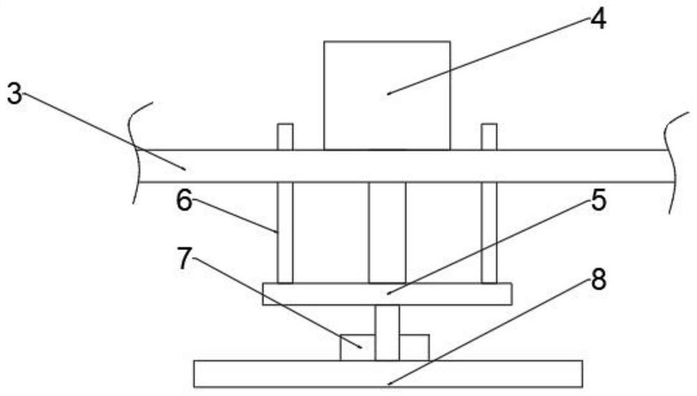
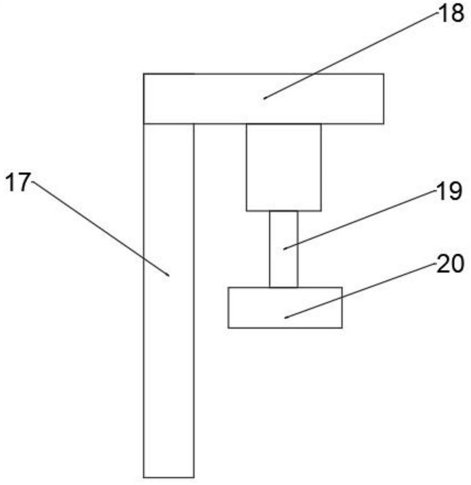
[0021] Embodiment one, by figure 1 , figure 2 and image 3 Given, the present invention includes a base 1, a support frame 2 is connected to both sides of the upper end of the base 1, a horizontal plate 3 is fixedly connected to one side of the upper part of the support frame 2, and a first hydraulic cylinder 4 is connected to the middle part of the upper end of the horizontal plate 3. The output end of the cylinder 4 runs through the horizontal plate 3, the output end of the first hydraulic cylinder 4 is connected with a partition 5, both sides of the upper end of the partition 5 are connected with round rods 6, and the middle part of the lower end of the partition 5 is rotatably connected with the first bearing 7, the first The lower end of the bearing 7 is connected with the first pressure plate 8, the middle part of the upper end of the base 1 is connected with the casing 9, the lower part of the casing 9 is connected with the motor 11, the output end of the motor 11 is ...

Embodiment 2

[0022] Embodiment 2, on the basis of Embodiment 1, the upper end of the round rod 6 runs through and extends to the upper part of one side of the horizontal plate 3 to open a through hole, the round rod 6 is located in the through hole, and the round rod 6 is slidably connected with the through hole, which is convenient Round bar 6 moves up and down.

Embodiment 3

[0023] Embodiment 3, on the basis of Embodiment 1, sound-absorbing partitions 10 are connected to both sides of the inner wall of the box body 9 to reduce noise.


PUM


Abstract

The invention relates to the technical field of numerical control machine tool edge folding, discloses a numerical control machine tool edge folding mechanism for metal plate machining. The problems that most edge folding devices at present are poor in edge folding effect, the edge folding position cannot be automatically adjusted in the edge folding process, time is wasted, and the working efficiency is reduced are solved. The numerical control machine tool edge folding mechanism comprises a base, the two sides of the upper end of the base are each connected with a supporting frame, one sidesof the upper portions of the supporting frames are fixedly connected with a transverse plate, the middle of the upper end of the transverse plate is connected with a first hydraulic cylinder, and theoutput end of the first hydraulic cylinder penetrates through the transverse plate. According to the numerical control machine tool edge folding mechanism, a first pressing plate is driven by the first hydraulic cylinder to move downwards, accordingly, a metal material is in a pressed state, a third hydraulic cylinder drives an edge folding plate to move downwards, second hydraulic cylinders drive third pressing plates to move forwards, thus, the metal material is subjected to secondary edge folding, and the edge folding effect is better; and a motor drives a rotating shaft to rotate, accordingly, the first pressing plate and a second pressing plate rotate at the same time to fold edges of different positions of the metal material, and the edge folding efficiency is improved.

Description

technical field [0001] The invention belongs to the technical field of numerical control machine tool hemming, in particular to a numerical control machine tool hemming mechanism for metal plate processing. Background technique [0002] The metal decorative panel is actually a metal decorative panel, and its meaning Metal decorative panel: refers to a novel interior decoration material compounded with metal as the surface material, and is installed with metal plates and block decorative materials through inlaying or structural connections. And other crafts and the decorative layer formed on the surface of the wall. [0003] During the production process of the metal sheet, it is folded, but most of the folding devices have poor folding effect, and the folding position cannot be automatically adjusted during the folding process, which wastes time and reduces work efficiency. Therefore, it is necessary to design The utility model relates to an edge folding mechanism of a nume...

Claims


Application Information

Patent Timeline
IPC IPC(8): B21D19/08B21D43/00
CPCB21D19/08B21D43/003
Inventor 李云余
Owner 江苏云佳金属制品有限公司
Why Eureka
Try Eureka