Using driven shield and touch elements lock algorithm

A technology of touch interface and touch detection, which is applied in the direction of electrical components, computing, computer components, etc., and can solve problems such as wrong detection of touch devices and changing capacitance

Pending Publication Date: 2021-03-09
TEXAS INSTR INC
View PDF0 Cites 0 Cited by
  • Summary
  • Abstract
  • Description
  • Claims
  • Application Information

AI Technical Summary

Problems solved by technology

Additionally, liquid present on a capacitive touch sensor can create an electrical connection between the sensor and surrounding grounded components of a capacitive touch sensor system, causing the sensor to change capacitance and causing the touch device to falsely detect a user touch

Method used


Image

  • Using driven shield and touch elements lock algorithm
  • Using driven shield and touch elements lock algorithm
  • Using driven shield and touch elements lock algorithm

Examples


Embodiment Construction

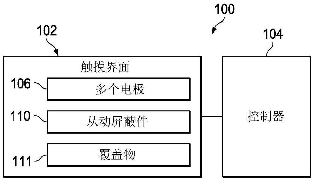
[0018] Capacitive touch devices and methods that may be more resilient to the presence of liquids are described. refer to figure 1 , shows a block diagram of the touch detection system 100 . Touch detection system 100 includes touch interface 102 coupled to controller 104 . The touch interface 102 includes a plurality of electrodes 106 and a driven shield 110 . The driven shield 110 may include electrodes. In some embodiments, the plurality of electrodes and driven shield 110 correspond to traces or pads on a printed circuit board (PCB). Controller 104 may be included on the same PCB as touch interface 102 . In the example shown, touch interface 102 also includes overlay 111 . Covering 111 may correspond to a layer positioned adjacent to plurality of electrodes 106 and driven shield 110 . The cover 111 may include plastic or another material, and may include touch buttons corresponding to the plurality of electrodes 106 .

[0019] Controller 104 corresponds to a microco...


PUM


Abstract

An apparatus includes a touch interface (102) that includes a plurality of electrodes (106) and a shield device (110). The shield device (110) is configured to establish a first mutual capacitive coupling with a first electrode of the plurality of electrodes (106). The shield device (110) is further configured to establish a second mutual capacitive coupling with a second electrode of the plurality of electrodes (106). The apparatus further includes a controller (104) coupled to the touch interface (102). The controller (104) is configured to detect a touch based on a detected first capacitance value of the first mutual capacitive coupling and a detected second capacitance value of the second mutual capacitive coupling.

Description

Background technique [0001] Capacitive touch detection technology has been used in many touch-driven devices, such as touch screens and keypads. Such touch-driven devices include a plurality of sensors and detect touch locations based on measured capacitance changes of the sensors. For example, a user's finger near a sensor may cause the capacitance of one of the sensors to increase or decrease, thereby causing the touch-driven device to detect a touch at the location of the sensor. However, the presence of liquid on the surface of a capacitive touch sensor can interfere with touch detection. For example, liquid present on the surface of a capacitive touch sensor can establish an electrical connection between a first sensor and a second sensor such that a user touching the first sensor can affect the capacitance of both the first sensor and the second sensor. Additionally, liquid present on a capacitive touch sensor can create an electrical connection between the sensor and ...

Claims


Application Information

Patent Timeline
IPC IPC(8): G06K11/06G08C21/00
CPCG06F2203/04107G06F3/0443G06F3/04186H03K17/9622H03K2217/960765H03K2217/960705H03K2217/94026H03K2217/960775G06F3/044H05K5/065G07C9/00674G06F3/0416
Inventor 罗一丁
Owner TEXAS INSTR INC
Why Eureka
Try Eureka