Gas turbine and method to operate the gas turbine

A technology of gas turbine and fluid path, which is applied in the direction of combustion method, gas turbine device, turbine/propulsion fuel delivery system, etc., to achieve the effects of stable control, cost reduction and system cost reduction

Inactive Publication Date: 2015-03-25
ANSALDO ENERGIA IP UK LTD
View PDF6 Cites 0 Cited by
  • Summary
  • Abstract
  • Description
  • Claims
  • Application Information

AI Technical Summary

Problems solved by technology

[0004] Taking into account the prior art, the problem of providing a gas turbine system and a method of operating a gas turbine system with stable control during transitional changes in the system is solved

Method used


Image

  • Gas turbine and method to operate the gas turbine
  • Gas turbine and method to operate the gas turbine
  • Gas turbine and method to operate the gas turbine

Examples


Embodiment Construction

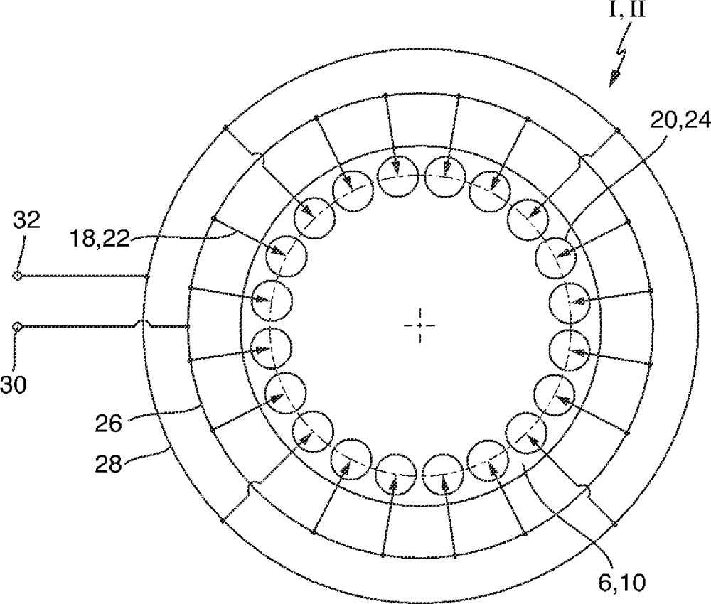
[0076] figure 1A gas turbine 2 with sequential combustion is shown schematically in an exemplary embodiment. The gas turbine 2 includes a compressor 4 , a first combustor 6 , a first turbine 8 , a second combustor 10 and a second turbine 12 . Typically, the gas turbine 2 includes a generator 14 arranged at the cold end of the gas turbine 2 , ie at the compressor 4 , coupled to a shaft 16 of the gas turbine 2 . Fuel, gas or oil is introduced via a fuel supply 18 to a burner 20 of the first combustor 6 , mixed with air compressed in the compressor 1 and combusted. The hot gases are partially expanded in the following first turbine 8 .

[0077] A fuel supply 22 supplies combustion fluid to a burner 24 of the second combustor 10 . The burners 20 of the first burner 6 are said to belong to a group. The burners 24 of the second burner 10 are said to belong to the second group. Groups 6 and 10 are therefore referred to using the reference numerals in a more general manner. Of c...


PUM


Abstract

It is proposed a gas turbine and a method to operate the gas turbine. A fluid is supplied to the gas turbine by means of fluid paths (40, 42, 44). A first fluid path (40) is divided into a second and third fluid path (42, 44). A first control valve (60) controls a fluid mass flow in the first fluid path (40). A second control valve (62) controls a ratio (64) of fluid mass flows in the second and third fluid paths (42, 44).

Description

technical field [0001] The claimed invention relates to gas turbines and methods of operating gas turbines. Background technique [0002] Known gas turbine systems include different fuel injection stages. Each stage includes a corresponding control valve. [0003] DE 10 2006 015 529 A1 relates to a burner system with different fuel injection stages. Several valves are each connected to a corresponding fuel line. The fuel pipes are connected to corresponding fuel injection stages. The valve is controlled by means of the control equipment. Contents of the invention [0004] Taking into account the prior art, the problem of providing a gas turbine system and a method of operating the gas turbine system with stable control during transitional changes in the system is solved. [0005] According to the present disclosure, this problem is solved by providing a first control valve controlling the mass flow of fluid in the first fluid path and a second control valve controllin...

Claims


Application Information

Patent Timeline
IPC IPC(8): F02C7/22F02C7/228F02C9/26
CPCF02C7/228F23R3/346
Inventor S.R.谢尔C.高普A.黑梅斯R.克罗普顿E.A.米勒
Owner ANSALDO ENERGIA IP UK LTD
Why Eureka
Try Eureka