Downlink flow control method for F1-U interface of 5G base station
A flow control and interface technology, applied in the field of 5G communication, which can solve the problems of PDCP packet loss, mutual influence between bearers, and fullness.
- Summary
- Abstract
- Description
- Claims
- Application Information
AI Technical Summary
Problems solved by technology
Method used
Image

Examples
Embodiment 1
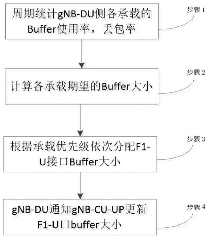
[0045] Such as figure 1 As shown, the downlink flow control method of the F1-U interface of the 5G base station includes:
[0046] Step 1, periodically count the Buffer usage rate and packet loss rate of each bearer on the gNB-DU side;
[0047] Step 2, calculate the expected Buffer size of each bearer according to the statistical information;
[0048] Step 3, allocate the Buffer size for the F1-U interface in turn according to the bearer priority;
[0049] Step 4, gNB-DU notifies gNB-CU-UP to update the Buffer size of the F1-U interface.
[0050] In step 1 of this embodiment, for each bearer, the following three statistical variables need to be maintained: the total number of received packets (total_receive_packet_cnt); the total Buffer usage rate (total_buffer_used_ratio) and the total number of dropped packets (total_drop_packet_cnt); The size of the currently allocated buffer is Buffer_alloc.
[0051] After the start of each statistical cycle, the statistical variables ...
Embodiment 2
[0067] In this embodiment, taking the base station having one downlink bearer RB_1 as an example, the control method in this application is described, and the control method includes:
[0068] Step S1.1: The gNB-DU side establishes the bearer RB_1, and allocates its actual allocation buffer:
[0069] Buffer_alloc=Buffer_1...(1),
[0070] Periodically count the Buffer usage rate and packet loss rate of RB_1 after the cache is allocated;
[0071] Step S1.2: At the end of each cycle, calculate the expected buffer Buffer_need for carrying RB_1 according to the statistical information in step S1.1:
[0072] Step S1.21: If the packet loss rate>0, then:
[0073] Buffer_need=Buffer_alloc*(1+Ratio_1)...(2);
[0074] Otherwise, go to step S1.22;
[0075] Step S1.22: If the Buffer usage rate>Thrsh_1, then:
[0076] Buffer_need=Buffer_alloc*(1+Ratio_2)...(3);
[0077] Otherwise, go to step S1.23;
[0078] Step S1.23: If the Buffer usage rate
[0079] Buffer_need=Bu...
Embodiment 3
[0086] In this embodiment, the base station has two downlink bearers RB_1 and RB_2 as an example, where the priority of RB_1 is higher than that of RB_2, and the control method in this application is described, and the control method includes:
[0087] Step S2.1: The gNB-DU side establishes two bearers RB_1 and RB_2, allocates their actual allocation buffer Buffer_alloc(i)=Buffer(i), and then periodically counts the Buffer usage rate and packet loss rate of the bearers RB_1 and RB_2, where, i represents the bearer ID (value 1 or 2);
[0088] Step S2.2: At the end of each cycle, calculate the expected buffer Buffer_need(i) for carrying RB_1 and RB_2 according to the statistical information in step S2.1:
[0089] Step S2.21: If the packet loss rate>0, then:
[0090] Buffer_need(i)=Buffer_alloc(i)*(1+Ratio_1),
[0091] Otherwise, go to step 2b;
[0092] Step S2.22: If the Buffer usage rate>Thrsh_1, then:
[0093] Buffer_need(i)=Buffer_alloc(i)*(1+Ratio_2),
[0094] Otherwise...
PUM
 Abstract
Description
Claims
Application Information
 - Generate Ideas
- Intellectual Property
- Life Sciences
- Materials
- Tech Scout
- Unparalleled Data Quality
- Higher Quality Content
- 60% Fewer Hallucinations
Browse by: Latest US Patents, China's latest patents, Technical Efficacy Thesaurus, Application Domain, Technology Topic, Popular Technical Reports.
© 2025 PatSnap. All rights reserved.Legal|Privacy policy|Modern Slavery Act Transparency Statement|Sitemap|About US| Contact US: help@patsnap.com