
Over-temperature load reduction device and method of optical storage integrated inverter

An inverter and load reduction technology, which is applied in the field of optical storage integrated inverters, can solve problems such as excessive heat, machine damage, and inability to effectively reduce equipment temperature.

Active Publication Date: 2021-03-09
江苏为恒智能科技有限公司
View PDF7 Cites 0 Cited by
  • Summary
  • Abstract
  • Description
  • Claims
  • Application Information

AI Technical Summary

Problems solved by technology

[0005] In summary, the input and output of the solar-storage integrated inverter may be 1-2 channels, and the same module will switch between the input side and the output side in different modes. If the photovoltaic inverter is directly used to control the output by limiting the The method of inverter temperature, when limiting the output, cannot limit the power of any one of the two specific inputs. Although the output is limited, it is possible that the power of the original lower power will become smaller, while the original higher power The power of the main heat source remains the same, or even the power becomes larger, generating more heat, which cannot effectively reduce the temperature of the equipment and cause machine damage

Method used


Image

  • Over-temperature load reduction device and method of optical storage integrated inverter
  • Over-temperature load reduction device and method of optical storage integrated inverter
  • Over-temperature load reduction device and method of optical storage integrated inverter

Examples


Embodiment 1

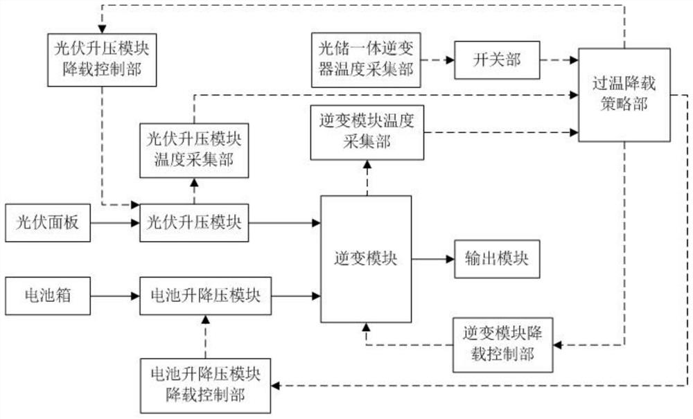
[0115] Such as figure 1 As shown, the photovoltaic booster module is equipped with a photovoltaic booster module temperature acquisition unit, which continuously collects the temperature value of the photovoltaic booster module; the inverter module is equipped with an inverter module temperature acquisition unit, which continuously collects the inverter module The temperature value of the integrated optical-storage inverter is equipped with an integrated optical-storage inverter temperature collection unit, which continuously collects the overall temperature value inside the integrated optical-storage inverter.

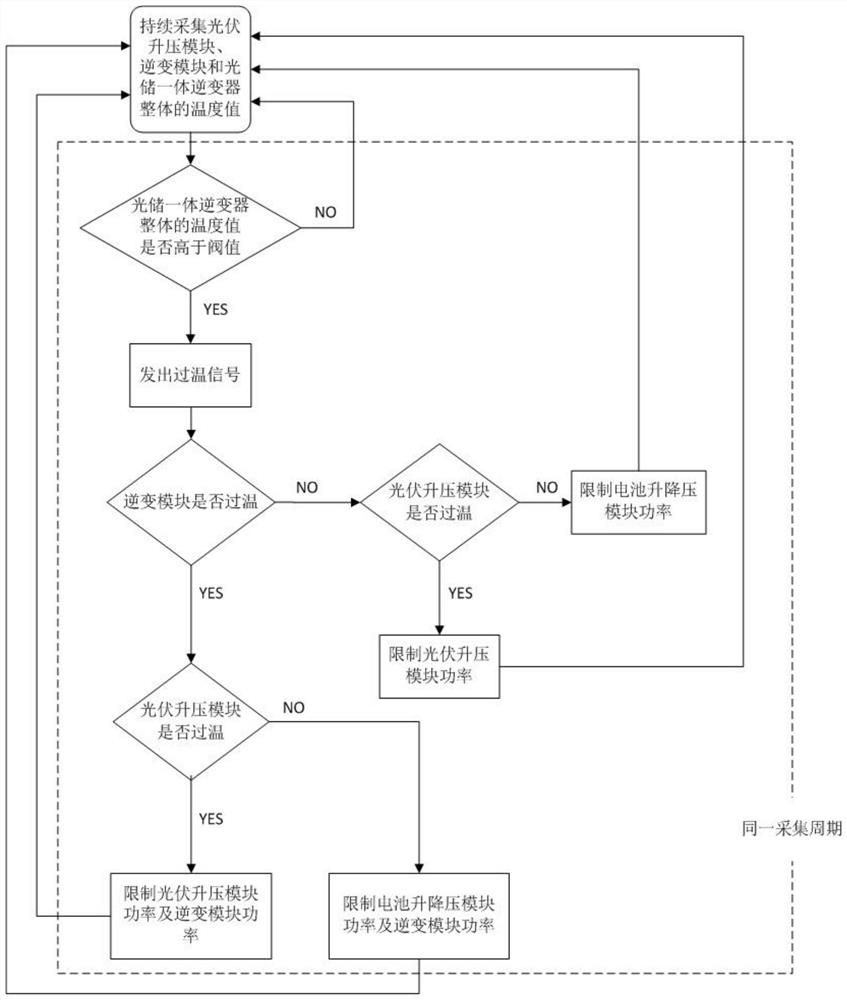
[0116] The switch unit compares the temperature value of the above-mentioned integrated optical-storage inverter in each collection cycle continuously and in real time with the preset threshold value. When the overall temperature value of the integrated optical-storage inverter in a certain collection cycle is higher than the threshold value, send an over-temperature ...

Embodiment 2

[0137] Such as Figure 4 The over-temperature load reduction device of the integrated optical-storage inverter shown in the figure is equipped with a temperature acquisition unit of the battery buck-boost module on the battery buck-boost module, which continuously collects the temperature value of the battery buck-boost module; on the inverter module There is an inverter module temperature acquisition unit, which continuously collects the temperature value of the inverter module; an optical-storage integrated inverter temperature acquisition unit is installed inside the optical-storage integrated inverter, which continuously collects the overall temperature of the optical-storage integrated inverter temperature value.

[0138] The switch unit compares the temperature value of the above-mentioned integrated optical-storage inverter in each collection cycle continuously and in real time with the preset threshold value. When the overall temperature value of the integrated optical...

Embodiment 3

[0159] Such as Figure 6 The over-temperature load reduction device of the photovoltaic-storage integrated inverter shown in the figure is equipped with a photovoltaic booster module temperature acquisition unit on the photovoltaic booster module, which continuously collects the temperature value of the photovoltaic booster module; There is a temperature collection unit of the battery buck-boost module, which continuously collects the temperature value of the battery buck-boost module; an inverter module temperature collection unit is arranged on the inverter module, which continuously collects the temperature value of the inverter module.

[0160] Over-temperature load reduction strategy department, which continuously receives the temperature value of the photovoltaic booster module, the temperature value of the battery buck-boost module, and the temperature value of the inverter module, and continuously compares it with the corresponding preset threshold value to determine th...


PUM


Abstract

The invention discloses an over-temperature load reduction device and method for an optical storage integrated inverter, and the inverter comprises a photovoltaic boost module, a battery boost-buck module, an inversion module, a photovoltaic boost module temperature collection part and / or a battery boost-buck module temperature collection part, an inversion module temperature collection part, an optical storage integrated inverter temperature collection part, a switch part, an over-temperature load reduction strategy part, a photovoltaic boost module load reduction control part, a battery buck-boost module load reduction control part and an inverter module load reduction control part;the over-temperature load reduction device operates continuously when the photovoltaic-energy storage integrated inverter operates. For the optical storage integrated inverter with multiple inputs and the same module capable of switching between the input and the output in different modes, the invention provides a device and a method for specifically limiting the power of each input after output, so that the overall temperature of the optical storage integrated inverter during working is effectively controlled, the main heat source of the photovoltaic-energy storage integrated inverter is effectively suppressed, and the service life of the machine is prolonged.

Description

technical field [0001] The invention relates to the field of integrated optical storage inverters, in particular to an over-temperature load reduction device and method for integrated optical storage inverters. Background technique [0002] An inverter is a converter that converts DC power into constant frequency and constant voltage or frequency modulation and voltage modulation AC power. During the working process, heat will be generated due to loss. If the internal temperature is too high, the service life of the equipment will be reduced. Therefore, when the temperature is overheated, the inverter needs to be derated to reduce the loss, thereby reducing the temperature to ensure the inverter. life. [0003] A photovoltaic inverter is an inverter that converts the variable DC voltage generated by photovoltaic solar panels into mains frequency alternating current, which can be fed back to the commercial transmission system or used for off-grid grids. There is only one in...

Claims


Application Information

Patent Timeline
IPC IPC(8): H02M1/32H02J7/35H02J7/00H02J3/38G05F1/66
CPCH02M1/32H02J7/35H02J7/00309H02J3/381G05F1/66H02J2300/24Y02E10/56
Inventor 王祥顾月明廖细文张杜钱敏华徐中彦
Owner 江苏为恒智能科技有限公司
Learn More