A vernier magnetic gear compound motor

A composite motor and magnetic gear technology, applied in magnetic circuits, synchronous machines, electromechanical devices, etc., can solve the problems of low electromagnetic torque density, low utilization rate of permanent magnets, and increase the thickness of air gaps, so as to improve the working magnetic density. and maximum transmission torque, improving torque density and utilization of magnetic steel, and increasing the effect of electromagnetic output torque

Active Publication Date: 2022-03-18
HUAZHONG UNIV OF SCI & TECH
View PDF0 Cites 0 Cited by
  • Summary
  • Abstract
  • Description
  • Claims
  • Application Information

AI Technical Summary

Problems solved by technology

However, this solution still has some problems that restrict the improvement of torque density: 1. The motor part generally adopts a permanent magnet synchronous motor with fractional slot concentrated winding, and the selection of pole pairs is difficult to increase due to the restriction of magnetic gears, so the electromagnetic torque density is low. It is not as good as the vernier motor using the principle of magnetic field modulation; 2. The magnetic circuit coupling between the motor and the magnetic gear, the working magnetic field of the motor and the magnetic gear must pass through the multi-layer air gap to close, which reduces their working magnetic field strength, which is not conducive to the motor torque and The torque transmission of the magnetic gear is improved; 3. The inner permanent magnet rotor adopts a surface mount structure, and is surrounded and fixed by a non-magnetic metal frame, which increases the thickness of the air gap and reduces the working magnetic field of the air gap
(M. Johnson, M.C. Gardner, H.A. Toliyat, S. Englebretson, W. Ouyang, and C. Tschida, "Design, Construction, and Analysis of a Large-Scale Inner Stator Radial Flux Magnetically Geared Generator for Wave Energy Conversion," IEEE Transactions on Industry Applications, vol.54, no.4, pp. 3305–3314, Jul.2018, doi:10.1109 / TIA.2018.2828383.) The disadvantage of this solution is that the inner and outer layers of the permanent magnet rotor have permanent magnets of opposite polarity The magnetic field weakens each other, so that the utilization rate of the permanent magnet is not high; and only the radial permanent magnet works, so that the inner and outer magnetic circuits need a thicker iron core yoke to close the magnetic circuit, which increases the volume and quality of the permanent magnet rotor

Method used


Image

  • A vernier magnetic gear compound motor
  • A vernier magnetic gear compound motor
  • A vernier magnetic gear compound motor

Examples


Embodiment Construction

[0026] In order to make the object, technical solution and advantages of the present invention clearer, the present invention will be further described in detail below in conjunction with the accompanying drawings and embodiments. It should be understood that the specific embodiments described here are only used to explain the present invention, not to limit the present invention. In addition, the technical features involved in the various embodiments of the present invention described below can be combined with each other as long as they do not constitute a conflict with each other.

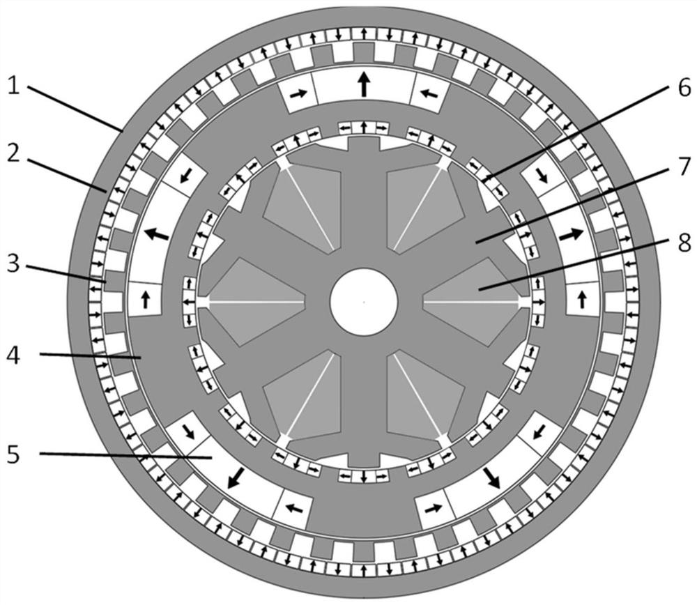
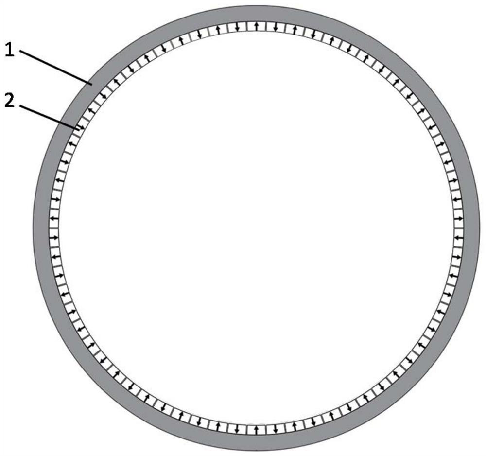
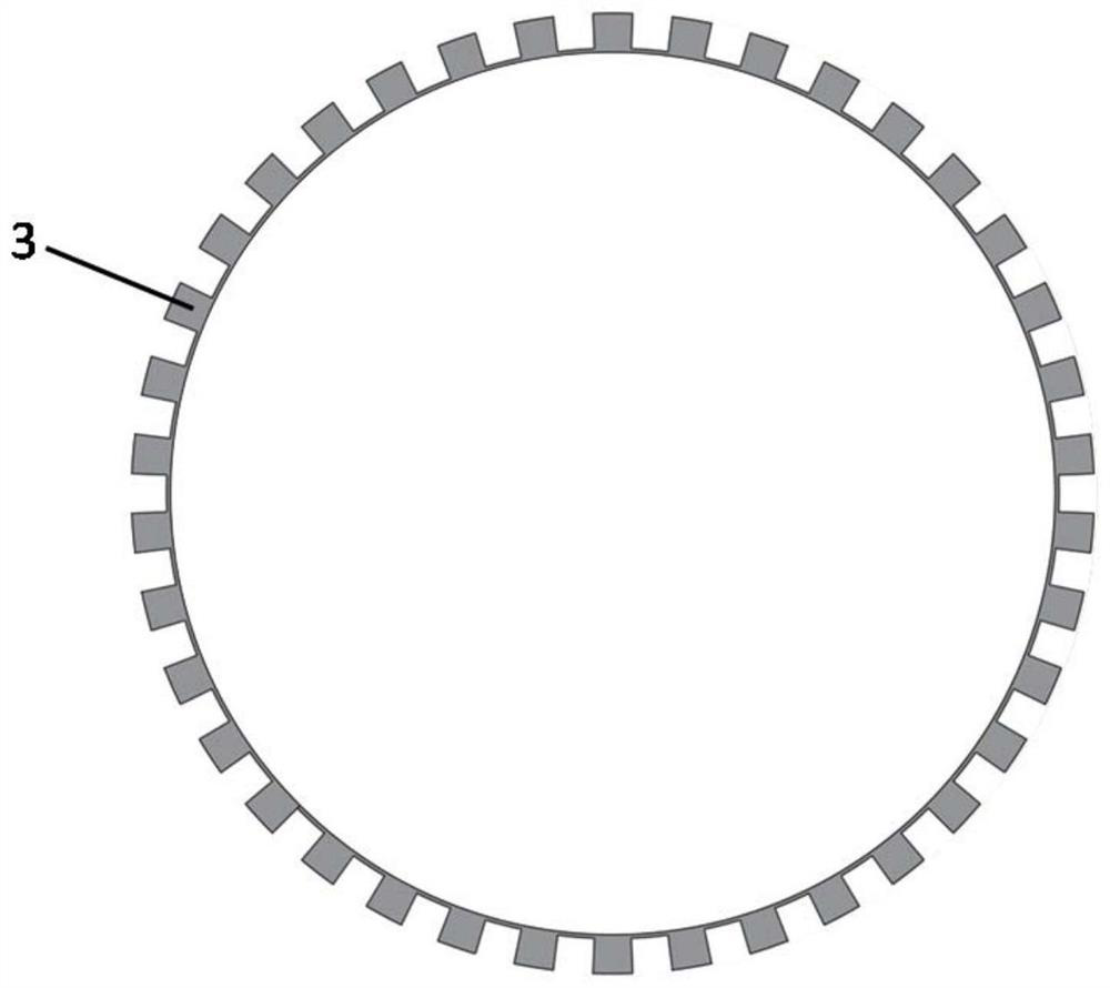
[0027] figure 1 Shown is a schematic structural view of the vernier magnetic gear compound motor provided by the embodiment of the present invention, including an outer permanent magnet stator, a modulating ring rotor, a permanent magnet inner rotor and an inner armature stator; an outer stator, a modulating ring rotor, a permanent magnet inner rotor and The inner stators are arranged concentri...


PUM


Abstract

The invention discloses a vernier magnetic gear composite motor, which belongs to the field of low-speed high-torque direct drive motors. The vernier magnetic gear composite motor provided by the present invention increases the electromagnetic output torque under the same volume and loss by changing the traditional fractional slot concentrated winding permanent magnet motor into a split tooth vernier motor; by adopting a double-layer Halbach alternating pole permanent magnet rotor structure , The working magnetic field with different pole pairs is generated in the inner and outer air gaps, which shortens the magnetic flux path of the magnetic gear and permanent magnet motor and the thickness of the rotor yoke, and improves the working flux density and maximum transmission torque of the magnetic gear. In summary, the vernier magnetic gear compound motor provided by the present invention can realize low-speed high-torque output through the change and optimization of the motor type and permanent magnet rotor structure, and has higher torque than the traditional magnetic gear compound motor density and magnet utilization.

Description

technical field [0001] The invention belongs to the field of low-speed high-torque direct drive motors, and more specifically relates to a vernier magnetic gear compound motor. Background technique [0002] The magnetic gear compound motor is a new type of motor that has gradually emerged with the magnetic field modulation magnetic gear. It is a technology that combines the magnetic field modulation magnetic gear with the permanent magnet motor to achieve low-speed high-torque output. According to the number of air gaps and the degree of coupling of the composite motor, different forms are derived, including the three-layer air-gap magnetic gear composite motor with the permanent magnet motor and the gear magnetic circuit separated, and the two-layer air gap collimation motor with the closed slot stator embedded with magnetic steel. Drive magnetic gear compound motor and so on. The above magnetic gear compound motor structures mainly realize the multiplexing of the rotor st...

Claims


Application Information

Patent Timeline
Patent Type & Authority Patents(China)
IPC IPC(8): H02K1/2753H02K1/2783H02K1/17H02K21/02H02K16/00
CPCH02K1/2753H02K1/17H02K21/025H02K16/00H02K2201/03H02K2213/03
Inventor 李大伟黄海林曲荣海黄以波郭文文
Owner HUAZHONG UNIV OF SCI & TECH
Why Eureka
Try Eureka