


Quick Research
Generate reliable direction feasibility study reports for your R&D in just a few steps.

Technical Q&A
Discover and master advanced knowledge NOW. Basics, ideas, possibilities, all at once.

Find Solutions
As an expert in R&D theories, this can generate solutions to your technical problems instantly.

Evaluate Feasibility
Analyze your overall solution with one click, know your potential R&D risks in advance.

Monitor Landscape
Get weekly tech updates, stay abreast of the latest tech innovations and key insights.
Windproof telescopic antenna structure
An antenna structure and antenna technology, applied in antennas, folded antennas, antenna components, etc., can solve problems such as performance loss, metal device influence, and inability to ensure absolute sealing, so as to reduce the possibility, inhibit the growth of microorganisms, and reduce electrical Effects of chemical corrosion effects and moisture effects
- Summary
- Abstract
- Description
- Claims
- Application Information
AI Technical Summary
Problems solved by technology
Method used
Image

Examples
Embodiment 1
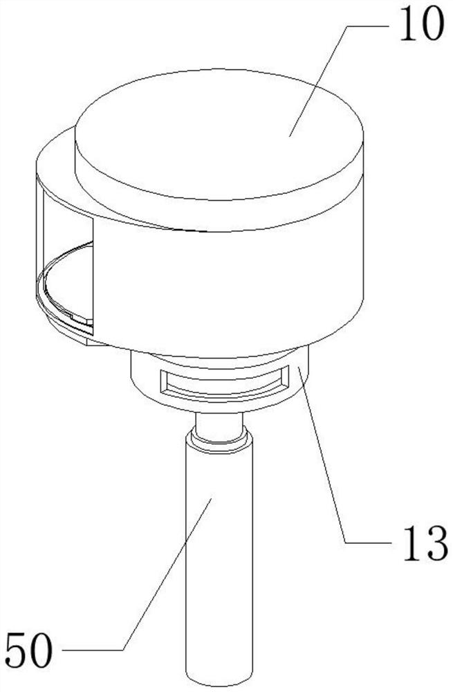
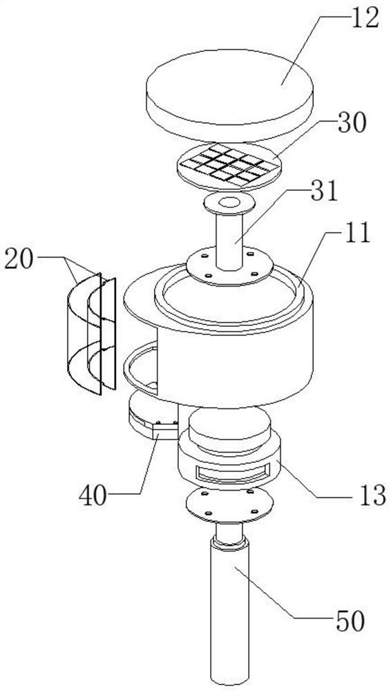
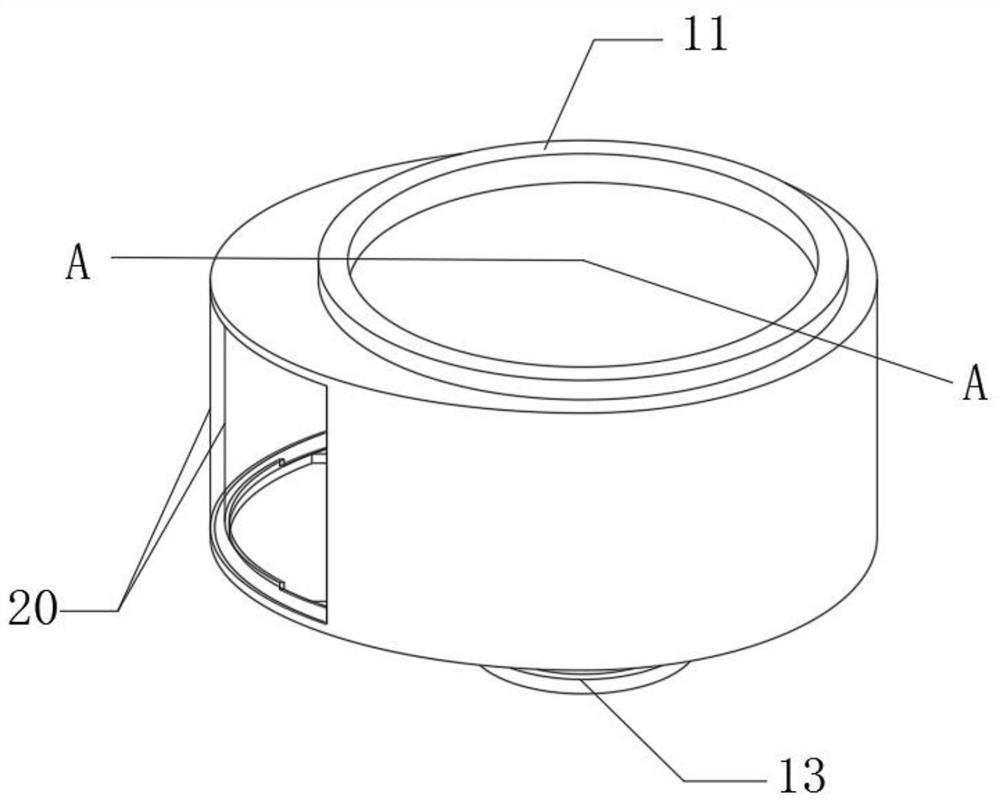
[0052] Embodiment 1: as Figure 1-10 As shown, a windproof retractable antenna structure includes a radome 10 . A hollow channel is provided on the side of the radome 10, and the hollow channel is covered with a double-layer glass part 20 and an air chamber is formed on the cover body of the radome 10; An air duct is arranged on the air duct, and a dew condensation plate 43 is arranged in the air duct, and the dew condensation plate 43 is specifically a metal plate; the radome 10, the double-layer glass part 20, and the dew condensation device 40 form a closed accommodation space; the double-layer glass part 20 is composed of an inner glass 21 and an outer glass 22 from the inside of the radome 10 to the outside; the top of the inner glass 21 is provided with a first gap 211 to form a first passage connecting the air chamber and the accommodation space; The bottom of the layer of glass is provided with a second notch 212, the air channel of the dew condensation device 40 is a...
Embodiment 2
[0057] Embodiment 2: Based on Embodiment 1, the radome 10 includes a housing 11, the top of the housing 11 is provided with an opening, and the housing cover 12 is connected to the opening; the inside of the housing cover 12 is an antenna cavity 121, and the antenna 30 is placed in the antenna cavity 121 Inside.
[0058] The horizontal position of the antenna cavity 121 in the housing cover 12 is higher than the horizontal position of the first channel. When the antenna 30 is placed in the antenna cavity 31 , it can ensure that the antenna as a whole is in a relatively high temperature environment. In addition, adopting such a structure facilitates the daily maintenance and cleaning of the antenna by the user. In order to ensure the tightness between the housing 11 and the housing cover 12 , a sealing gasket can be provided between the housing 11 and the housing cover 12 , since it is a prior art solution, it will not be repeated here.
Embodiment 3
[0059] Embodiment 3: Based on Embodiment 2, a rotating device 13 is connected to the bottom of the housing 11, and a telescopic rod 50 is fixedly connected to the bottom of the rotating device 13; the housing 11 and the telescopic rod 50 can be relatively rotated by the rotating device.
[0060] The rotating device 13 is a manual device, including a rotating part and a base. The kinematic pair formed by the two adopts the rotating pair in the lower pair, and is a sliding friction pair. With this structure, one needs to overcome frictional resistance for rotation, so avoid External force especially sea wind causes improper rotation of the radome, and the second is that the radome and the telescopic rod can be coaxially arranged.
PUM
 Abstract
Description
Claims
Application Information
 - R&D Engineer
- R&D Manager
- IP Professional
- Industry Leading Data Capabilities
- Powerful AI technology
- Patent DNA Extraction
Browse by: Latest US Patents, China's latest patents, Technical Efficacy Thesaurus, Application Domain, Technology Topic, Popular Technical Reports.
© 2024 PatSnap. All rights reserved.Legal|Privacy policy|Modern Slavery Act Transparency Statement|Sitemap|About US| Contact US: help@patsnap.com