
Reflector adjustable device

A mirror and placement technology, applied in the field of laser projectors, can solve problems such as difficulty in adjusting mirrors, and achieve the effect of reasonable design and good practical application value

Pending Publication Date: 2021-03-09
SHANXI OVISION OPTRONICS CO LTD
View PDF0 Cites 2 Cited by
  • Summary
  • Abstract
  • Description
  • Claims
  • Application Information

AI Technical Summary

Problems solved by technology

However, in the prior art, it is relatively difficult to adjust the reflector fixed in the projector

Method used


Image

  • Reflector adjustable device
  • Reflector adjustable device
  • Reflector adjustable device

Examples


Embodiment Construction

[0020] Specific embodiments of the present invention will be described in detail below in conjunction with the accompanying drawings.

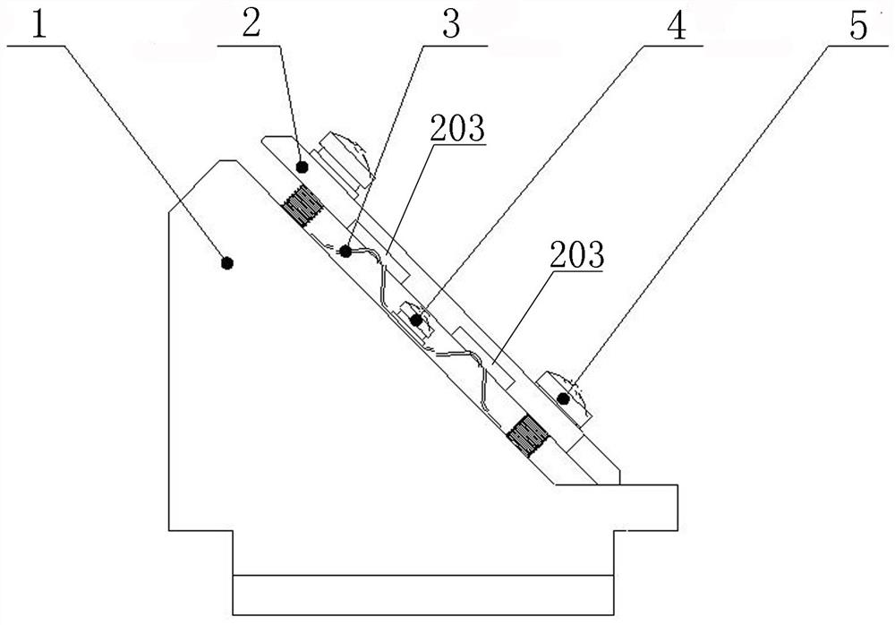
[0021] A mirror adjustable device, such as figure 1 As shown, a reflector bracket 1 is included, and a reflector holder 2 is installed on the reflector bracket 1 .

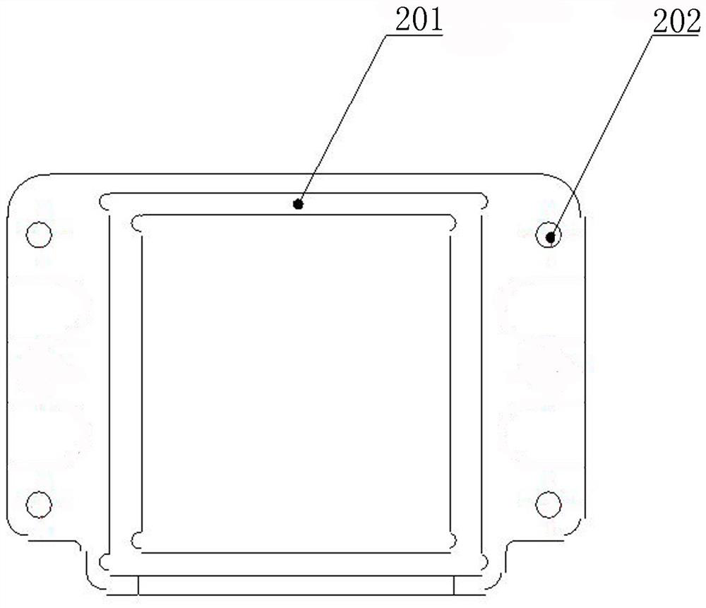
[0022] Such as figure 2 As shown, the four corners of the mirror fixing base 2 are respectively reserved with mirror adjustment screw fixing holes 202 , and the middle part of the mirror fixing base 2 is used as a mirror placement place 201 .

[0023] Such as figure 1 As shown, shrapnels are symmetrically installed on both sides of the reflector bracket 1 .

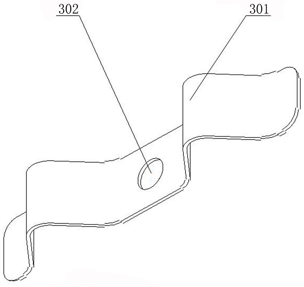
[0024] Such as image 3 As shown, a spring fixing hole 302 is reserved in the middle of the spring 3 , and the spring 3 is symmetrically provided with bending and pressing portions 301 of the spring.

[0025] Such as figure 1 As shown, the elastic sheet 3 passes through the elastic sheet fixing screw 4 through the elas...


PUM


Abstract

The invention discloses a reflector adjustable device which comprises a reflector support 1, a reflector fixing seat 2, elastic pieces 3, an elastic piece fixing screw 4 and reflector adjusting screws5. When the device is used, a reflector is placed on the reflector fixing seat firstly, the reflector can be prevented from being scratched or crushed due to the fact that the reflector makes directcontact with the elastic pieces in the adjusting process due to the structural design, and then the reflector fixing seat is fixed to the reflector support through screws. Meanwhile, the elastic pieces on the two sides are fixed to the reflector support through screws, the elastic pieces are provided with bent pressing contact parts, the bent pressing contact parts have good elasticity, and it isguaranteed that the elastic piece pressing contact parts can abut against the reflector fixing seat all the time in the screwing-in and screwing-out process of the adjusting screws. And meanwhile, thefine adjustment effect of the reflector can be realized by screwing the four adjusting screws into or out of the support.

Description

technical field [0001] The invention relates to the technical field of laser projectors, in particular to an adjustable reflector fixed in the projector. Background technique [0002] The optical path system plays a very important role in laser projection. When the laser emits light, it needs to be refracted by lenses with different curvatures to produce high-brightness parallel light. In order to save the space of the optical path, it is necessary to use mirrors to change the direction of the optical path during this process. [0003] The mirror uses the law of reflection to convert the optical path to different angles or directions. In practical applications, due to errors caused by optical path design, machining technology, and assembly technology, there is a certain deviation in the position of the mirror. In the optical path system, if the position of the reflector shifts or the angle between the mirror and the optical path deviates slightly from the original design val...

Claims


Application Information

Patent Timeline
Patent Type & Authority Applications(China)
IPC IPC(8): G03B21/28G02B7/198
CPCG02B7/198G03B21/28
Inventor 陈海洋兰旭阳王永振胡元元王园
Owner SHANXI OVISION OPTRONICS CO LTD
Learn More