
Patsnap Eureka
For R&D, Patsnap Eureka makes reading and utilizing patents & technical documents easy.
Patsnap Eureka AIR
Designed for self-driven R&D workflows. Generate viable solutions, solve complex R&D challenges, empower your innovation with AI.

Patsnap Eureka Materials
Designed for material experts only. Revolutionize your material R&D, from search, analyze, to developing new materials.

TechResearch
Generate reliable direction feasibility study reports for your R&D in just a few steps.

TechSeek
Discover and master advanced knowledge NOW. Basics, ideas, possibilities, all at once.

TechMind
As an expert in R&D Theories, TechMind can generates customized viable solutions instantly.

TechRisk
Analyze your overall solution with one click, know your potential R&D risks in advance.

TechMonitor
Get weekly tech updates, stay abreast of the latest tech innovations and key insights.
A fuel plate surface contamination location detection device and system
A positioning detection device and surface detection technology, applied in the field of nuclear detection, can solve the problems of low degree of automation and low detection efficiency, and achieve the effects of high degree of automation, high detection efficiency, and avoidance of secondary pollution
- Summary
- Abstract
- Description
- Claims
- Application Information
AI Technical Summary
Problems solved by technology
Method used
Image


Examples
Embodiment 1
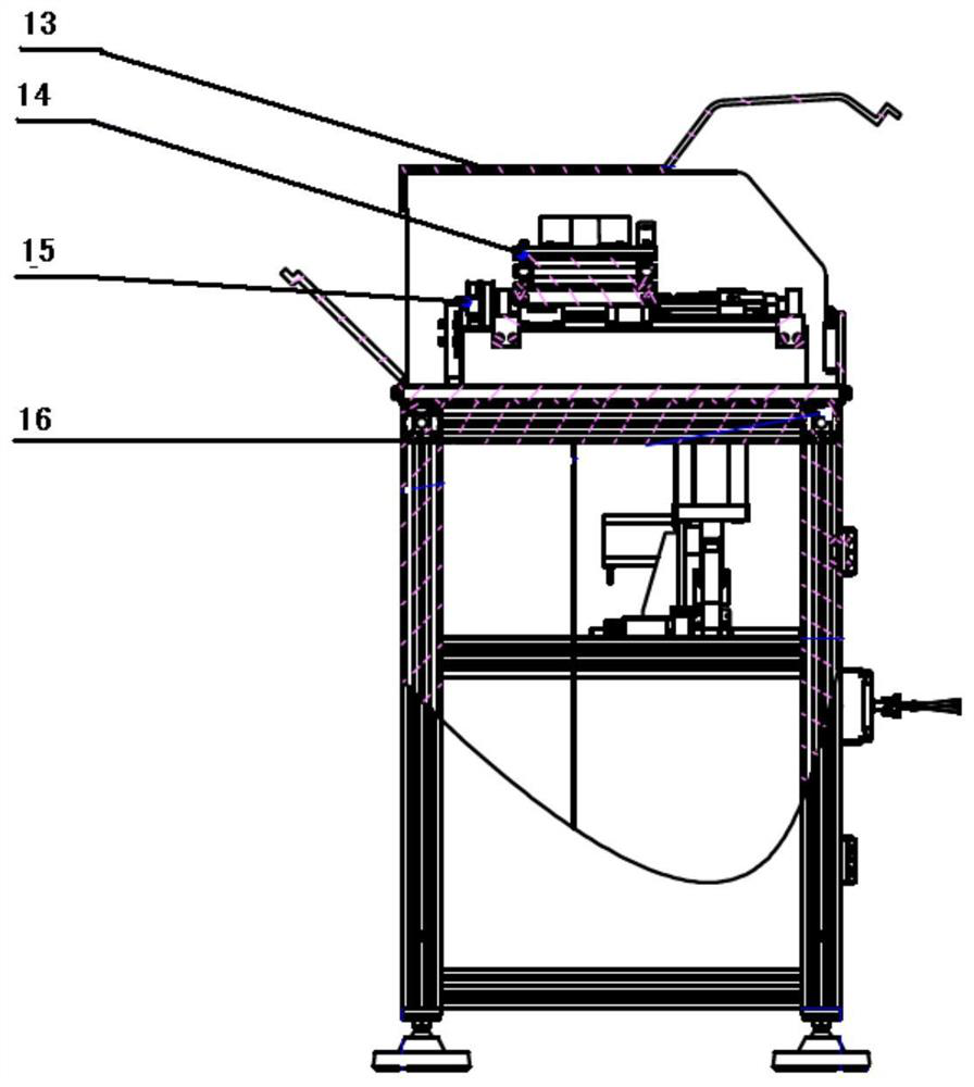
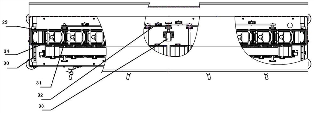
[0033] This embodiment proposes a fuel plate surface pollution location detection device, such as Figure 1-3 As shown, the fuel plate surface contamination location detection device includes: the detection device includes a shield 13, an upper surface detection unit 27, a lower surface detection unit 28, a lifting unit, a workpiece transfer unit and a support mechanism 16; wherein the shield 13 It is fixed on the support mechanism 16 and forms a cavity with the support mechanism 16 to accommodate the upper surface detection unit 27 , the lower surface detection unit 28 , the lifting unit and the workpiece transfer unit arranged on the support mechanism 16 . For the convenience of subsequent description, this embodiment refers to figure 2 front view of and image 3 In the top view of the support mechanism, the left-right direction (ie, the length direction) of the support mechanism is defined as the transverse direction, and the front-to-back direction (ie, the width directi...
Embodiment 2
[0043] Based on the fuel plate surface pollution location detection device proposed in the above embodiment 1, this embodiment proposes a fuel plate surface pollution location detection system, such as Figure 4 Said, the detection system includes a signal processing device 5, a host computer 7, a power supply device 1 and a fuel plate surface contamination location detection device 3 (that is, the fuel plate surface contamination location detection device proposed in the above-mentioned embodiment 1); the power supply device 1 Power supply for the signal processing device 5, the upper computer 7 and the fuel plate surface contamination location detection device 3 respectively; The processing means 5 are connected in communication.
[0044] Specifically, in this embodiment, the power supply device 1 adopts a regulated power supply, and the host computer adopts a computer; the regulated power supply 1 is connected to the surface pollution detection device 3 through the power co...
PUM
 Abstract
Description
Claims
Application Information
 - R&D Engineer
- R&D Manager
- IP Professional
- Industry Leading Data Capabilities
- Powerful AI technology
- Patent DNA Extraction
Browse by: Latest US Patents, China's latest patents, Technical Efficacy Thesaurus, Application Domain, Technology Topic, Popular Technical Reports.
© 2024 PatSnap. All rights reserved.Legal|Privacy policy|Modern Slavery Act Transparency Statement|Sitemap|About US| Contact US: help@patsnap.com