


Quick Research
Generate reliable direction feasibility study reports for your R&D in just a few steps.

Technical Q&A
Discover and master advanced knowledge NOW. Basics, ideas, possibilities, all at once.

Find Solutions
As an expert in R&D theories, this can generate solutions to your technical problems instantly.

Evaluate Feasibility
Analyze your overall solution with one click, know your potential R&D risks in advance.

Monitor Landscape
Get weekly tech updates, stay abreast of the latest tech innovations and key insights.
Layered grouting device and application thereof
A technology of grouting device and grouting pipe, which is applied in the direction of protective devices, sheet pile walls, buildings, etc., can solve the problems of poor layered grouting effect, etc., and achieve the effect of improving sealing effect, strong flexibility, and increasing service life
- Summary
- Abstract
- Description
- Claims
- Application Information
AI Technical Summary
Problems solved by technology
Method used
Image

Examples
Embodiment 1
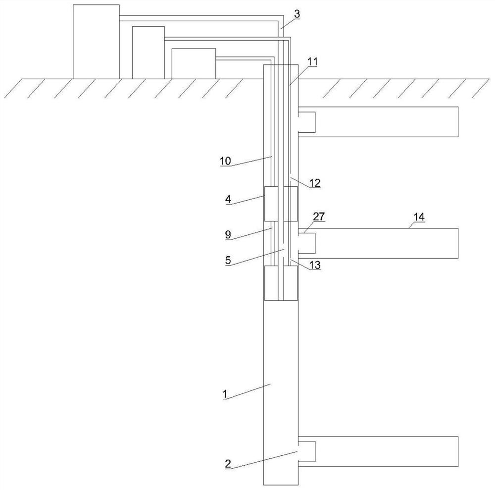
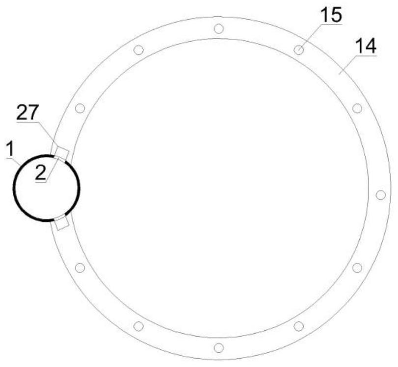
[0039] combine Figure 1-4 , this embodiment provides a layered grouting device, including a grouting pipe 1, similar to the traditional grouting pipe 1, in order to be able to grout at different heights, on the side wall of the grouting pipe 1 from top to bottom A plurality of grouting holes 2 are opened, and each grouting hole 2 is at the same position on the grouting pipe 1 as the position to be grouted. In order to avoid the grouting of the grouting pipe 1 at the same time, The defect that the grouting effect cannot be achieved in some positions due to the outflow of the holes 2 needs to meet the requirement that one grouting hole 2 can be grouted alone and the rest of the grouting holes 2 should not be grouted during grouting;
[0040]In order to meet the above-mentioned requirements in this embodiment, a grout supply pipe 3 with an outer diameter smaller than the inner diameter of the grout pipe 1 is firstly installed in the grout pipe 1, and the grout pipe 1 body is not...
Embodiment 2
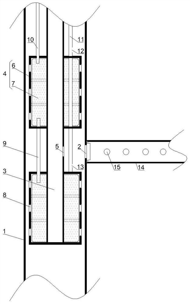
[0049] combine Figure 5 , This embodiment provides a layered grouting device, the equipment structure is similar to that of Embodiment 1, the main difference is that the grout stopper 4 is improved. In this embodiment, the outer casing 6 is specifically composed of an upper cover 16 distributed coaxially, a plurality of middle supporting layers 17 and a lower cover 18, all of which are sleeved on the slurry supply pipe 3 and screwed to its outer wall, and the upper The cover 16 is specifically composed of a first transverse circular plate 19 and a first annular vertical enclosure 20 integrated with the first transverse circular plate 19 and arranged at the bottom of its outer edge. The middle support layer 17 is specifically composed of a cylindrical cavity 21 and the second annular vertical shroud 22 arranged on the outer edge of the top end and the outer edge of the bottom end of the cylindrical cavity 21, the lower cover 18 is specifically composed of a second transverse c...
Embodiment 3
[0054] combine Image 6 , in this embodiment, the equipment structure is the same as in Embodiment 2, the main difference is that, in order to effectively utilize the gap between the adjacent cylindrical elastic sealing cavity 25 to expand the exposed part, it is filled with oil in this embodiment to improve the sealing Therefore, it is necessary to expand the cylindrical elastic sealing cavity 25 at the bottom of each grout plug 4 to contact the inner wall of the grouting pipe 1 before supplying oil. Therefore, in this embodiment, each high-pressure pipe 26 also has A pressure valve 28 is fixedly installed, and the pressure valve 28 is bidirectional, and its opening only needs to meet the pressure requirement. In the pipe 26, under normal pressure, it is affected by its own stretchability, and the pressure relief hole is in a state of being squeezed and closed by itself. When the positive pressure or negative pressure in it reaches the opening pressure, the pressure relief ho...
PUM
 Abstract
Description
Claims
Application Information
 - R&D Engineer
- R&D Manager
- IP Professional
- Industry Leading Data Capabilities
- Powerful AI technology
- Patent DNA Extraction
Browse by: Latest US Patents, China's latest patents, Technical Efficacy Thesaurus, Application Domain, Technology Topic, Popular Technical Reports.
© 2024 PatSnap. All rights reserved.Legal|Privacy policy|Modern Slavery Act Transparency Statement|Sitemap|About US| Contact US: help@patsnap.com