
High-power polarization-maintaining optical fiber and preparation method thereof

A high-power, optical fiber technology, applied in glass manufacturing equipment, manufacturing tools, etc., can solve the problem of low output power of polarization-maintaining optical fiber, improve heat transfer efficiency, reduce viscosity difference and linear expansion coefficient difference, increase pump The effect of Puguang's input

Active Publication Date: 2021-03-09
JIANGSU FASTEN OPTOELECTRONICS TECH
View PDF5 Cites 6 Cited by
  • Summary
  • Abstract
  • Description
  • Claims
  • Application Information

AI Technical Summary

Problems solved by technology

[0005] Aiming at the problem of low output power of rare earth-doped polarization-maintaining optical fiber, this application designs a new polarization-maintaining erbium-ytterbium co-doped optical fiber, additionally doping alkali metal in the fiber core, and designing a three-cladding structure, in order to achieve Higher power pump light input with good linear polarization performance

Method used


Image

  • High-power polarization-maintaining optical fiber and preparation method thereof
  • High-power polarization-maintaining optical fiber and preparation method thereof
  • High-power polarization-maintaining optical fiber and preparation method thereof

Examples


Embodiment 1

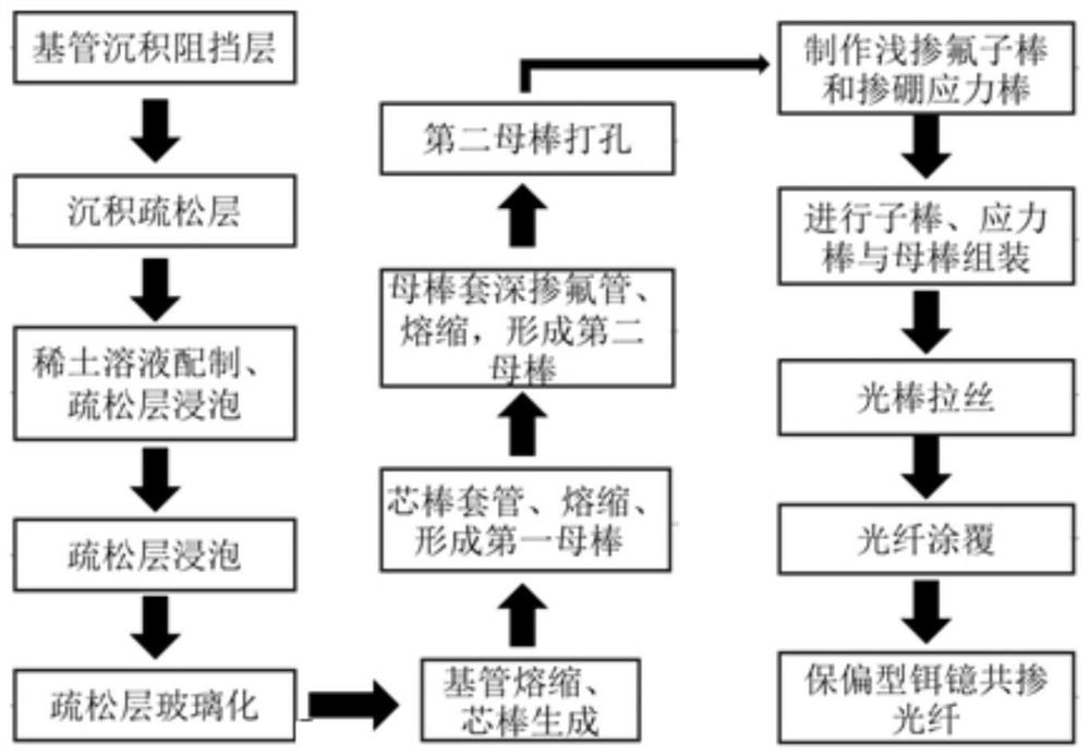
[0049] Such as figure 1 As shown, the preparation process of the biasing fiber in this embodiment is as figure 1 As shown, in order to facilitate understanding, the preparation process of the introduction of the branched three-clad 镱-blended optical fiber having a circular cross section is taken as an example.

[0050] The first step: First, the barrier layer is deposited in the inner wall of the base pipe, and the size of the outer diameter of 25 to 35 mm, the wall thickness is 2.5 to 3.5 mm, and the fluctuation value of the outer diameter of the base tube and the wall thickness is required to be 2 SF 6 Gas, polish it in the inner surface, the polishing time is 5 ~ 10 min; after design, deposit the barrier layer, into the base tube into SiCl 4 (Traffic: 200 ~ 300sccm) and O 2 (Flow: 1200sccm), sf 6 (Flow: 500 ~ 600sccm) The deposition temperature is controlled at 1700 to 1750 ° C, and the deposition barrier layer is controlled at 0.2 to 0.3 mm, and the glass transition is perfo...

Embodiment 2

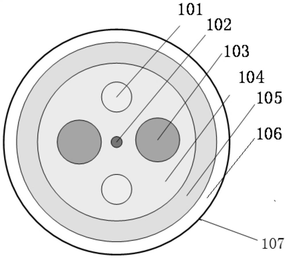
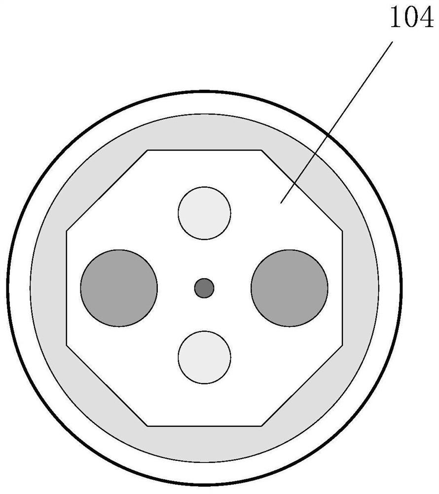
[0062] Example 1 The cross-sectional structure of the obtained high-power polarizing fiber was inwardly included inwardly including the core 102, the first cladding layer 104, the second cladding 105, the outer clad layer 106, and the outer coating 107.

[0063] The core 102 is 0.08%, and the diameter D1 is 25 μm relative to the purity difference of the purity.

[0064] The first cladding layer 104 is filled with two shallow fluorine-based rods along the core 102 to form a fluorine region (101), and the refractive index difference Δ2 relative to the purity quartz is -0.08%, fluor fluor fluor region. 101) Diameter D2 is 80 μm.

[0065] The first cladding layer 104 also fills two blending strain stress rods along the core 102 to constitute a stress zone 103, and the refractive index difference Δ3 with respect to the purity of the purity is -0.6%, the stress zone (103) diameter. D3 is 110 μm.

[0066] The symmetrical axis of the fluorine region 101 and the symmetric axis of the stres...


PUM

PropertyMeasurementUnit
diameteraaaaaaaaaa
diameteraaaaaaaaaa
diameteraaaaaaaaaa

Abstract

The invention relates to a high-power polarization-maintaining optical fiber and a preparation method thereof, and belongs to the technical field of polarization-maintaining optical fibers. The crosssection structure of the optical fiber sequentially comprises a fiber core (102), a first cladding (104), a second cladding (105), an outer cladding (106) and an external coating (107) from inside tooutside, the fiber core (102) is fluorine-doped quartz containing rare earth, alkali metal and a dispersing agent, and the first cladding (104) is filled with two shallow fluorine-doped quartz rods symmetrically distributed along the fiber core (102) to form a fluorine-doped area (101); the first cladding (104) is also filled with two stress rods which are symmetrically distributed along the fibercore (102) to form a stress area (103); and the symmetry axis of the fluorine-doped area (101) and the symmetry axis of the stress area (103) perpendicularly intersect at the center of the fiber core(102). According to the optical fiber, the existence of spiral light can be reduced to a greater extent, the input of pump light is increased, the reflection frequency of a cladding is improved, thereflection path is shortened, and the effects of reducing the optical power density and improving the laser output power are achieved.

Description

Technical field [0001] The present invention relates to an aerated type optical fiber, which belongs to the field of optical and laser optoelectronic technology. Background technique [0002] In recent years, the sharp increase in high-power fiber laser demand has stimulated the development of coherent synthesis technology, especially line-polarized fiber lasers in ultra-high power coherent synthetic lasers and high-precision fiber laser radar detection technology are more and more extensive applications. One of the necessary conditions to achieve coherent synthesis technique is to make the light signal retain line polarization state, and the most mainstream scheme is currently the laser system of the full fiber optic line relative to the use of polarizing devices to achieve simple operation, simple structure. This requires the gain fiber to have both gain amplification function, but also has excellent polarization retention characteristics, and therefore, a polarized molded-blen...

Claims


Application Information

Patent Timeline
Patent Type & Authority Applications(China)
IPC IPC(8): C03B37/027
CPCC03B37/02709C03B37/02718C03B37/02736
Inventor 宋海瑞冯术娟缪振华侯树虎卞新海徐律韩婷婷赵霞周震华
Owner JIANGSU FASTEN OPTOELECTRONICS TECH
Learn More