
Design method of automobile air conditioner airflow channel

A technology of airflow channel and design method, applied in air handling equipment, vehicle components, heating/cooling equipment, etc., can solve the problems of chaotic airflow, increased occupant discomfort, unbearable overheating temperature, etc., to achieve the effect of uniform temperature

Pending Publication Date: 2021-03-09
的卢技术有限公司
View PDF0 Cites 0 Cited by
  • Summary
  • Abstract
  • Description
  • Claims
  • Application Information

AI Technical Summary

Problems solved by technology

[0003] The current air-conditioning air outlet system has the following problems. After the air is blown out from the air-conditioning outlet, the airflow in the passenger compartment is too chaotic. There is no channel for the airflow, so that the kinetic energy of the airflow after leaving the air-conditioning outlet is quickly consumed and converted into internal energy. It drives the air flow inside the passenger compartment well; unlike the natural wind, the air from the air conditioner is too direct, and blowing it for a long time will bring discomfort to the occupants, and it is difficult to bear the overheating temperature without blowing it; the uniformity of the temperature adjustment of the air conditioner is not good , the unevenness of heat and cold will increase the discomfort of the occupants

Method used


Image

  • Design method of automobile air conditioner airflow channel
  • Design method of automobile air conditioner airflow channel
  • Design method of automobile air conditioner airflow channel

Examples


Embodiment 1

[0029] The present invention provides a design method of an automotive air conditioning airflow channel, and the specific method is as follows:

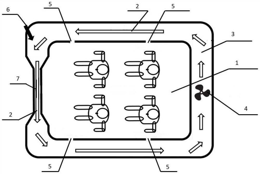
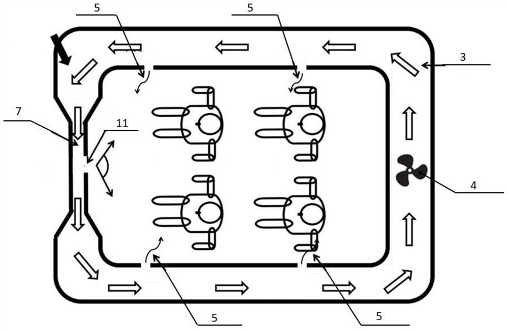
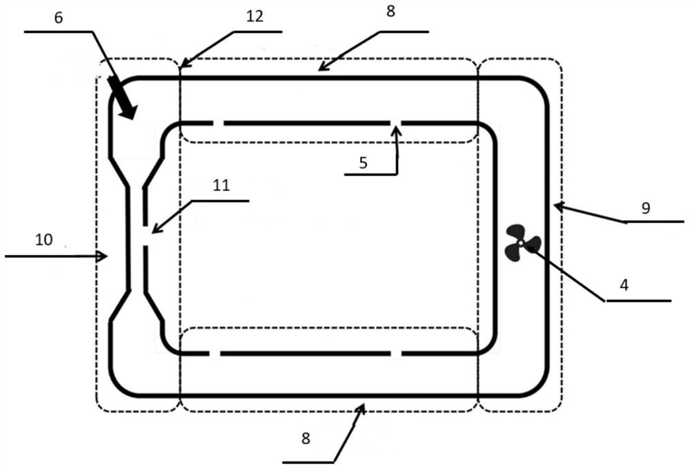
[0030] Step 1, such as Figure 1-4 As shown, the annular airflow passage is constructed in the automobile, the specific mode is: in the interior space of the automobile instrument, the airflow channel pipe 13 is laid in the two-sided door interlayer space 8 and the trunk space 9, and the above space is connected, in the door The opening and closing position uses a soft material joint 12 to turn the airflow channel pipe 13 interface, preferably, the soft material joint 12 employs rubber or silica gel; the air-conditioned air outlet 6 is provided, so that air conditioning blows The resulting gas stream 2 is circulated in the airflow channel instead of direct blowing to the car passenger compartment 1, thereby achieving the airflow cycle in the vehicle that can maintain a higher flow rate at a lower energy, and can realize the occupant faste...

Embodiment 2

[0036] Different from the first embodiment, the air flow passage is set to a dual channel according to the size of the car passenger compartment 1 and the car model configuration, and the passage is two sets of airflow 2 cycles in the circulation direction; makes it Airflow 2 will become more disabled, and the airflow 2 pairs of conversion will also be easier to implement.


PUM


Abstract

The invention discloses a design method of an air flow channel of an automobile air conditioner. The method comprises the following steps: constructing an annular airflow channel in an automobile, andarranging an air conditioner air outlet in the airflow channel; enabling air blown out by the air conditioner to circulate in the airflow channel; arranging a main flow area and one or more auxiliaryflow areas with different widths in the airflow channel according to the air flow speed requirement, and uniformly forming a plurality of air outlets leading to the interior of an automobile passenger compartment in the main flow area of the airflow channel, wherein the air holes are in a hole shape; and forming an auxiliary air outlet leading to an automobile passenger compartment in the auxiliary flow area of the airflow channel; and opening / closing the auxiliary air outlet as required. The air flow of the automobile air conditioner designed according to the method drives the air circulation speed in the passenger compartment to a greater extent, the air conditioner energy consumption is reduced, and meanwhile, the air conditioner is closer to natural wind to improve the passenger comfort.

Description

Technical field [0001] The present invention relates to the field of automotive air conditioning air conditioning, and more particularly to a design method for automotive air conditioning airflow channels. Background technique [0002] Keeping a certain temperature and appropriate air fluidity in the automobile passenger compartment helps to enhance the occupant's ride experience, and therefore generally regulate the temperature and air flow of the entire passenger compartment by mounting the air conditioning system. [0003] The current air conditioning outlet system has the following problems. After the airflow is blown from the air-conditioned mouth, the airflow flow in the passenger cabin is too confusing. There is no channel for airflow flows, which causes the airflow to leave the air-conditioned air outlet, and the kinetic energy is rapidly consuming into internal energy. Very good driving of the internal air flow; different from natural wind, air conditioning is too straig...

Claims


Application Information

Patent Timeline
IPC IPC(8): B60H1/34B60H1/26
CPCB60H1/34B60H1/26
Inventor 周小刚
Owner 的卢技术有限公司
Learn More