A cutting device for modifying a computer

A cutting device and computer technology, applied in the computer field, can solve problems such as affecting cutting and inconvenient adjustment of cutting angle

Active Publication Date: 2022-05-31
费莱(浙江)科技有限公司
View PDF13 Cites 0 Cited by
  • Summary
  • Abstract
  • Description
  • Claims
  • Application Information

AI Technical Summary

Problems solved by technology

The device realizes the rotation adjustment and front and rear adjustment of the cutting table by operating the angle adjustment mechanism and the cutting table, so that the computer can move forward and backward when being cut, and can also rotate the cutting table to adjust the angle, so as to meet the needs of computer modification. To improve the modification efficiency, the cutting device used for modifying the computer has the advantages of front and rear adjustment and rotation adjustment, but the cutting angle adjustment of the device is inconvenient, and the fixing device at the bottom will affect the cutting, so the device needs to be improved

Method used


Image

  • A cutting device for modifying a computer
  • A cutting device for modifying a computer
  • A cutting device for modifying a computer

Examples


Embodiment 1

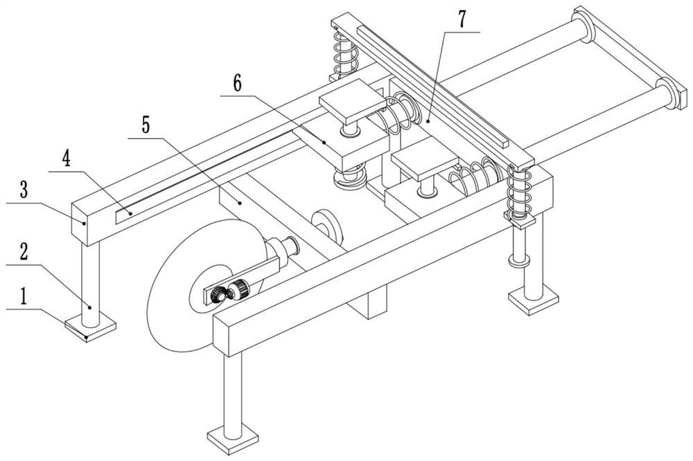
[0029] see Figure 1-6 , a cutting device for refitting a computer, comprising a fixed rod 3, the left and right sides of the lower surface of the fixed rod 3 are provided with support columns 2, the lower end of the support column 2 is provided with a cushion block 1, and the middle of the fixed rod 3 is provided with There is a chute 4, the middle part of the chute 4 is slidably connected to the end of the slider 6 away from the center of the device, the right end of the fixing rod 3 is provided with a second fixing plate 7, and the front and rear sides of the second fixing plate 7 are slidably connected to the second fixing plate 7. The guide rod 13, the left end of the second guide rod 13 is fixedly connected to the right side of the slider 6, a second spring 12 is arranged between the slider 6 and the second fixing plate 7, and the second spring 12 is sleeved on the second guide rod 13 Externally, the right end of the second guide rod 13 is provided with a push plate 14 ,...

Embodiment 2

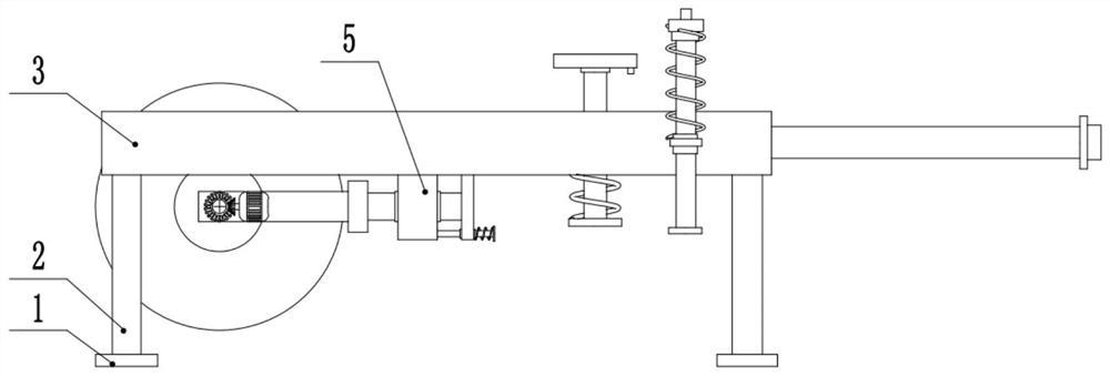
[0032] see Image 6 , the other contents of this embodiment are the same as those of the first embodiment, the difference is that the lower part of the rotating disk 30 is slidably connected to the limit rod 31 , the right end of the limit rod 31 is provided with a third limit block 33 , and the third limit A fourth spring 32 is provided between the position block 33 and the rotating disk 30 . In order to ensure that the angle of the cutting wheel 29 is locked during the cutting process, a limit rod 31 is provided at the right end of the rotating disk 30. When the rotating disk 30 is rotated, the limiting rod 31 can be pulled out to the right, and the rotating disk 30 It can be rotated freely. After the angle adjustment is completed, the limit rod 31 is released. Under the action of the fourth spring 32, the limit rod 31 moves to the left, and the left side of the limit rod 31 bears against the first fixing plate 5. , the angle of the rotating disk 30 is locked at this time. ...


PUM


Abstract

The invention relates to the technical field of computers, and discloses a cutting device for refitting a computer, which includes a fixed rod, the left and right sides of the lower surface of the fixed rod are provided with support columns, the middle part of the fixed rod is provided with a chute, and the chute The middle part is slidably connected to one end of the slider away from the center of the device, the right end of the fixed rod is provided with a second fixed plate, the front and rear sides of the second fixed plate are slidably connected to the second guide rod, and the left end of the second guide rod is fixedly connected to the slider On the right side of the slider, the middle part of the slider is slidably connected to the first guide rod, and the lower end of the first guide rod is fixedly connected to the first limit block. A first spring is arranged between the first limit block and the slider. The upper end of a guide rod is fixedly connected with the pressure plate, and the middle part of the lower surface of the fixed rod is provided with a first fixed plate. The invention is applicable to a cutting device used for refitting a computer. The cutting wheel can rotate around a rotating shaft, so that the cutting angle can be adjusted freely and in a more personalized manner.

Description

technical field [0001] The invention relates to the technical field of computers, in particular to a cutting device for refitting a computer. Background technique [0002] With the development of modern mechanical processing industry, the requirements for cutting quality and precision are constantly improving, and the requirements for improving production efficiency, reducing production costs, and having highly intelligent automatic cutting functions are also increasing. The development of CNC cutting machine must meet the requirements of the development of modern mechanical processing industry. Cutting machines are divided into flame cutting machines, plasma cutting machines, laser cutting machines, water cutting machines, etc. The laser cutting machine is the fastest in efficiency, the highest in cutting accuracy, and the cutting thickness is generally small. The cutting speed of the plasma cutting machine is also very fast, and the cutting surface has a certain slope. ...

Claims


Application Information

Patent Timeline
Patent Type & Authority Patents(China)
IPC IPC(8): B26D1/157B26D5/08B26D7/02B26D7/26
CPCB26D1/157B26D5/086B26D7/02B26D7/2635Y02W30/82
Inventor 葛斌
Owner 费莱(浙江)科技有限公司
Why Eureka
Try Eureka