U-shaped palate rod for invisible correction of molar distal movement patient and correction method

A technology of invisible orthodontics and invisible braces, applied in the field of stomatology, can solve problems such as enhanced anterior teeth anchorage, poor orthodontic effect, poor aesthetics, etc., to avoid repeated implantation, improve orthodontic efficiency, and high bonding strength.

Pending Publication Date: 2021-03-09
PEKING UNIV SCHOOL OF STOMATOLOGY
View PDF0 Cites 5 Cited by
  • Summary
  • Abstract
  • Description
  • Claims
  • Application Information

AI Technical Summary

Problems solved by technology

[0008] 1. Class II intermaxillary traction can only enhance the anchorage of the anterior teeth, but cannot protect the anchorage of the maxillary posterior teeth
Especially after the molars move far away, the narrowing of the braces leads to the forward movement of the molars, and Class II intermaxillary traction cannot be avoided
[0009] 2. Class II intermaxillary traction has a vertical elongation component for the upper anterior teeth, so it is not suitable for cases where the upper anterior teeth need to be depressed
In addition, Class II intermaxillary traction has vertical elongation and mesial movement components for the mandibular first molar, which is not suitable for cases with high angle and labial inclination of the lower anterior teeth
[0010] 3. Class II intermaxillary traction requires patients to remove and wear it by themselves, which requires high patient compliance. In clinical practice, it is difficult for many patients to insist on wearing Class II intermaxillary traction, and the correction effect is not good.
[0011] 4. Class II intermaxillary traction has certain risks for adult patients, which will cause changes in the jaw position, especially for patients with temporomandibular joint disorders
[0012] 5. Class II intermaxillary traction is located on the buccal side, with poor aesthetics
[0015] 2. Class II intermaxillary traction does not directly act on the maxillary molars, so the forward movement of the maxillary molars cannot be avoided
[0019] 1. Buccal implant-assisted traction can only enhance the anchorage of the anterior teeth, but cannot protect the anchorage of the maxillary posterior teeth
Especially after the molars have moved far away, the narrowing of the braces will inevitably lead to the forward movement of the molars
[0020] 2. The buccal implant requires two traumatic implants in the stage of maxillary dentition displacement, which increases the trauma and cost of the patient
[0021] 3. Buccal implant-assisted traction also requires patients to remove and wear it by themselves, which requires high patient compliance. In clinical practice, it is difficult for many patients to insist on wearing traction all the time, and the treatment effect is not good.
[0022] 4. The auxiliary traction of buccal implant nails is located on the buccal side, and the aesthetics are poor
[0024] 1. The buccal implant-assisted traction cannot directly act on the maxillary molars, so the forward movement of the maxillary molars cannot be avoided
[0025] 2. The maxillary molars and premolars on the buccal side are relatively close to the roots, and the position of the implant screws on the buccal side needs to be replaced when the molars move away.
[0027] 4. The rubber bands at the canines of the braces are less aesthetically pleasing

Method used


Image

  • U-shaped palate rod for invisible correction of molar distal movement patient and correction method
  • U-shaped palate rod for invisible correction of molar distal movement patient and correction method

Examples


Embodiment Construction

[0052] Exemplary embodiments of the present disclosure will be described in more detail below with reference to the accompanying drawings. Although exemplary embodiments of the present disclosure are shown in the drawings, it should be understood that the present disclosure may be embodied in various forms and should not be limited by the embodiments set forth herein. Rather, these embodiments are provided for more thorough understanding of the present disclosure and to fully convey the scope of the present disclosure to those skilled in the art.

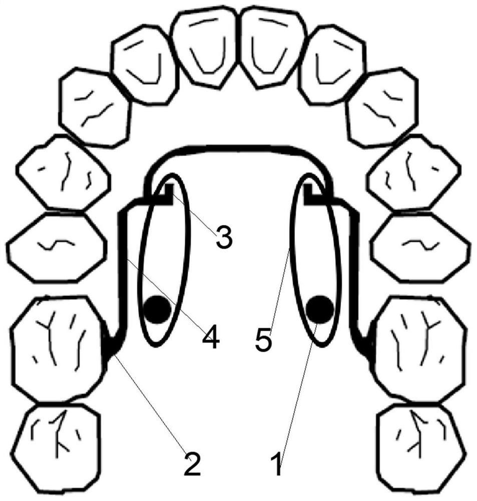
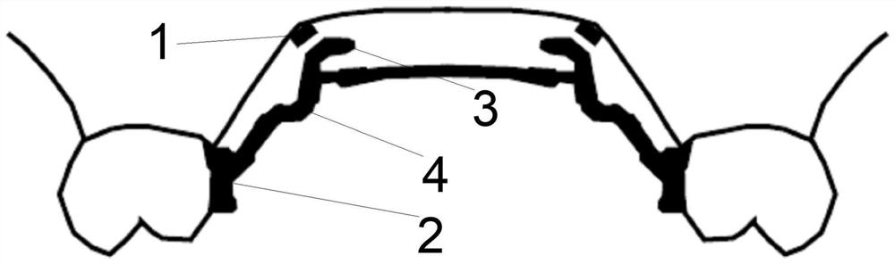
[0053] The U-shaped palatal bar designed by the present invention is used together with the existing invisible braces to correct the remote displacement of maxillary molars. The present invention designs a U-shaped palatal bar for invisible orthodontic treatment of patients with distant molars. The U-shaped palatal bar includes: a U-shaped palatal bar main body. U shape palate bar 4.

[0054] Specifically, there are two connecting...


PUM


Abstract

The invention discloses a U-shaped palate rod for invisible correction of a molar distal movement patient and a correction method. The U-shaped palate rod comprises two connecting bodies, two tractionhooks and a U-shaped palate rod body, wherein one end of each two connecting body is connected with the left and right first molar tongue sides of the upper jaw, and the other end of each two connecting body is connected with the two ends of the U-shaped palate rod body respectively; the connecting faces of the connecting bodies and the first molar tongue sides of the upper jaw keep away from thegingival margin by 2mm and keep away from the tongue tip by 2mm; the connecting faces wrap the mesial and distal parts of the first molar tongue sides of the upper jaw to increase the bonding area; abottom plate is subjected to gridding treatment; the U-shaped palate rod body is designed in the dental arch shape, and the palate mucosa is kept away from the U-shaped palate rod body by 2-3mm and does not make contact with the palate mucosa; and the two traction hooks are connected to the corners of the two sides of the front portion of the U-shaped palate rod body respectively and extend downwards and forwards. The U-shaped palate rod is used for stabilizing the rear tooth position during invisible correction of molar distal movement, the correction force can directly act on the upper jawmolars, molar mesial movement relapse is prevented, maximum adduction and congestion relief of the front teeth are facilitated, the correction efficiency is improved, the patient feels more comfortable, the correction efficiency is high, and the U-shaped palate rod is attractive and hidden.

Description

technical field [0001] The invention belongs to the technical field of stomatology, and in particular relates to a U-shaped palatal bar and an orthodontic method for invisible orthodontic treatment of patients with distant molars. Background technique [0002] In orthodontic treatment, the method of moving the maxillary molars away is often used to correct the molars’ distal relationship and relieve the crowding of the maxillary dental arch. Avoid patients with extraction of maxillary premolars. Invisible orthodontics without brackets are welcomed by adult patients due to its aesthetics and comfort. Invisible braces can wrap and strengthen the crown as a whole. At present, molar movement has become a tooth movement method that invisible orthodontics is good at. [0003] At present, studies have reported that the efficiency of invisible orthodontics in the stage of molars moving away has reached 80-90%, but it has been found clinically that the true efficiency of invisible o...

Claims


Application Information

Patent Timeline
Patent Type & Authority Applications(China)
IPC IPC(8): A61C7/00A61C7/08
CPCA61C7/002A61C7/08
Inventor 李巍然郭润智李林蔚黄一平王勇赵一姣吴威
Owner PEKING UNIV SCHOOL OF STOMATOLOGY
Why Eureka
Try Eureka