
Thermal power plant booster station power distribution device

A technology of power distribution device and step-up station, which is applied in substation/power distribution device housing, substation/switchgear cooling/ventilation, substation/switch layout details, etc., which can solve the problems of high foundation treatment cost, high operation and maintenance cost, Problems such as large footprint, to achieve the effect of increasing the range of air flow, solving the large amount of maintenance, and reducing the footprint

Pending Publication Date: 2021-03-05
フアネングチンメイルイジンパワージェネレーションカンパニーリミテッド
View PDF0 Cites 0 Cited by
  • Summary
  • Abstract
  • Description
  • Claims
  • Application Information

AI Technical Summary

Problems solved by technology

[0003] However, the existing power distribution device has problems such as large floor area, relatively high cost of foundation treatment, large amount of maintenance, and high later operation and maintenance costs. For this reason, we have introduced a power distribution device for the step-up station of thermal power plants

Method used


Image

  • Thermal power plant booster station power distribution device
  • Thermal power plant booster station power distribution device
  • Thermal power plant booster station power distribution device

Examples


Embodiment Construction

[0022] The following will clearly and completely describe the technical solutions in the embodiments of the present invention with reference to the accompanying drawings in the embodiments of the present invention. Obviously, the described embodiments are only some, not all, embodiments of the present invention. Based on the embodiments of the present invention, all other embodiments obtained by persons of ordinary skill in the art without making creative efforts belong to the protection scope of the present invention.

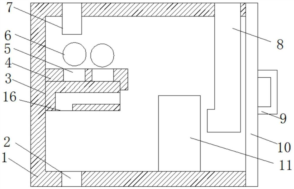
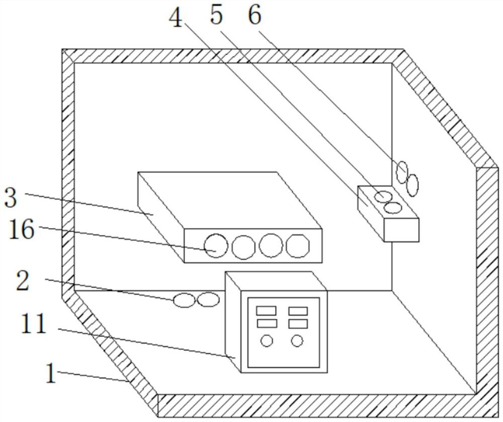
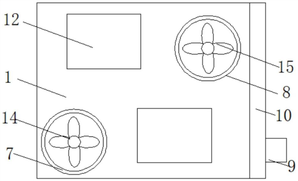
[0023] Such as Figure 1-6 As shown, the present invention provides a technical solution: a power distribution device of a step-up station in a thermal power plant, including a distribution box 1, a support column 12 is fixedly installed on the top of the distribution box 1, and an anti- The rain roof 13, the side of the distribution box 1 is hinged with a sealed door 10, the side of the sealed door 10 is provided with a handle 9, the top of the top of the dis...


PUM


Abstract

The invention relates to the technical field of thermal power plant booster stations, and discloses a thermal power plant booster station power distribution device which comprises a power distributionbox, a supporting column is fixedly installed at the top of the power distribution box, a rainproof roof is fixedly installed at the top of the supporting column, a sealing door is hinged to the sideface of the power distribution box, and a handle is arranged on the side face of the sealing door. An exhaust pipe and an air inlet pipe are arranged at the tops of the two sides of the top of the power distribution box in a penetrating mode, an exhaust fan is arranged in an inner cavity of the exhaust pipe, an air inlet fan is arranged in an inner cavity of the air inlet pipe, a wire arrangementplate is arranged on one side face of the inner cavity of the power distribution box, an L-shaped wire arrangement hole is formed in the wire arrangement plate, and a fixing plate is fixedly installed on the back wall of the inner cavity of the power distribution box. And a positioning hole is formed in the top of the fixing plate. The problems that the power distribution device is large in occupied area, relatively high in foundation treatment cost, large in maintenance amount, high in later operation and maintenance cost and the like are solved.

Description

technical field [0001] The invention relates to the technical field of booster stations in thermal power plants, in particular to a power distribution device for booster stations in thermal power plants. Background technique [0002] Power distribution device is assembled in closed or semiclosed metal safe by electrical wiring requirement by switchgear, measuring instrument, protective device and auxiliary equipment or on screen width, forms low-voltage distribution equipment. During normal operation, the circuit can be connected or disconnected by means of a manual or automatic switch. Cut off the circuit or alarm with the help of protective electrical appliances in case of failure or abnormal operation. Various parameters in operation can be displayed by means of measuring instruments, and some electrical parameters can also be adjusted to prompt or send out signals for deviations from normal working conditions. [0003] However, the existing power distribution device ha...

Claims


Application Information

Patent Timeline
IPC IPC(8): H02B1/56H02B1/46H02B1/28H02B1/20
CPCH02B1/202H02B1/28H02B1/46H02B1/565
Inventor 赖雪华吴利平邹火金叶敬
Owner フアネングチンメイルイジンパワージェネレーションカンパニーリミテッド
Learn More