Method for testing unmanned vehicles with moving targets on the road
A technology for unmanned vehicles and moving targets, applied in the field of obstacle avoidance systems, to achieve the effect of soft texture, perfect automation capability and light weight
- Summary
- Abstract
- Description
- Claims
- Application Information
AI Technical Summary
Problems solved by technology
Method used
Image
Examples
Embodiment 1
[0030] Embodiment 1: road test is a very important content of driverless car performance test. For unmanned vehicles, sometimes it is necessary to test their performance on different moving target roads and the ability to deal with emergencies. As an emerging technology, unmanned vehicle road test controls the steering and speed of the vehicle by sensing the road environment and obstacle information through the sensor system, so that the vehicle can drive safely and reliably on the road. At present, the technical conditions such as experimental methods and tools in this field are immature. Most of the moving trajectories of the existing test devices are fixed, the route planning is not systematic, and the accuracy of the moving target's trajectory is not high and does not have randomness. The availability of vehicle performance data is relatively small, which is not a good way to test the actual operating performance of self-driving cars.
[0031] The invention records a movi...
Embodiment 1
[0036] To further illustrate the device of the present invention, the following two assumptions are made. Embodiment 1: Assume that the driving trajectories are the same, but the moving speeds of the moving objects are different. Embodiment 2: Assume that the traveling speeds of the moving objects are the same, but the traveling paths are different. Embodiment 3: Assume that the moving target and the unmanned vehicle are traveling in the same direction.
Embodiment approach 1
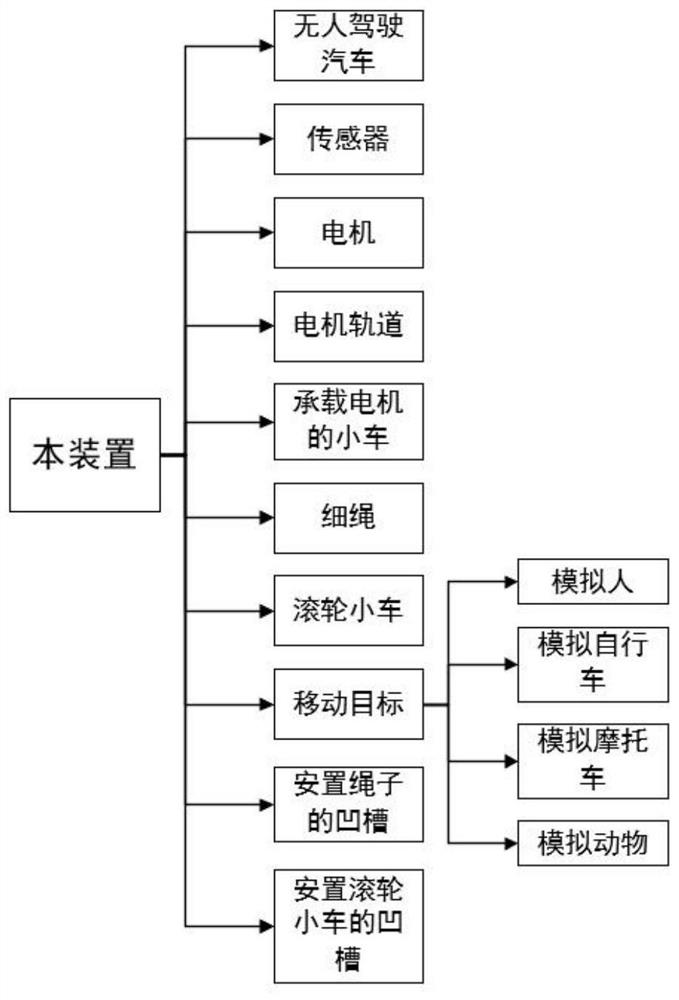
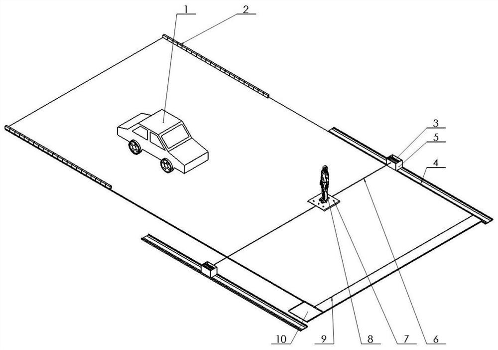
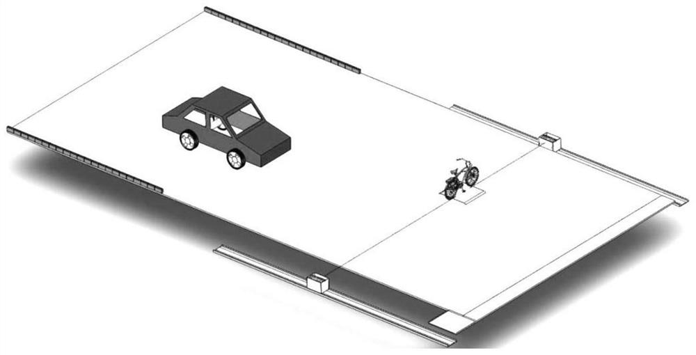
[0037] Embodiment 1: Assume that the driving trajectories are the same, but the moving speeds of the moving targets are different, such as Figure 4 shown. The moving target of the device of the present invention is various, and the specific implementation process is described in detail by mainly taking human equipment as an example. The human equipment runs at speeds of 0.5m / s, 0.8m / s, 1m / s, and 1.2m / s respectively, and is placed on the same driving route for testing each time. Fix the human device on the roller trolley, start the test, make the human device run to the left side of the road, control the speed of the motor on the rope to control the moving speed of the human device, the sensor detects that the car starts to run, and controls the moving target at 0.5m / s speed across the road to detect the detection function of the driverless car obstacle avoidance system. Use the same method to detect other speed devices. Even if the unmanned vehicle cannot accurately detec...
PUM
 Abstract
Description
Claims
Application Information
 - R&D
- Intellectual Property
- Life Sciences
- Materials
- Tech Scout
- Unparalleled Data Quality
- Higher Quality Content
- 60% Fewer Hallucinations
Browse by: Latest US Patents, China's latest patents, Technical Efficacy Thesaurus, Application Domain, Technology Topic, Popular Technical Reports.
© 2025 PatSnap. All rights reserved.Legal|Privacy policy|Modern Slavery Act Transparency Statement|Sitemap|About US| Contact US: help@patsnap.com


