Sleeve for fabricated wall surface

A prefabricated, sleeve technology, applied in covering/lining, construction, building structure, etc., can solve the problems of inability to be dedicated, disgusting, inconvenient, etc., and achieve the effect of simple structure and easy operation.

Pending Publication Date: 2021-03-05
ZHEJIANG YASHA DECORATION
View PDF0 Cites 0 Cited by
  • Summary
  • Abstract
  • Description
  • Claims
  • Application Information

AI Technical Summary

Problems solved by technology

The existing medical equipment belt installed on the bedside wall of the hospital bed has caused great inconvenience to both the medical staff and the patients. When the connector is inserted, it will disturb or hit the patient, or the patient will block the connector on the equipment belt or accidentally get an electric shock, which will cause life-threatening; and if such an exposed equipment belt is installed in an old-age apartment, it will also affect the interior decoration effect , the elderly may also feel disgusted and feel bad when they see the device belt when they live
[0003] The equipment belt is exposed and the panel is mostly opened with side-hung doors, which affects the space inside the sleeve and is inconvenient; or sliding doors generally have two exposed tracks, which is inconvenient to clean
[0004] In the prior art, most of the sleeves are circular tubes and straight tubes, and the internal structure of the sleeve is simple, which cannot be used in different environments, and cannot be used for special purposes, and there is no corresponding component that can be pressed and dislocated to be used in the installation of wall panels.

Method used


Image

  • Sleeve for fabricated wall surface
  • Sleeve for fabricated wall surface
  • Sleeve for fabricated wall surface

Examples


Embodiment 1

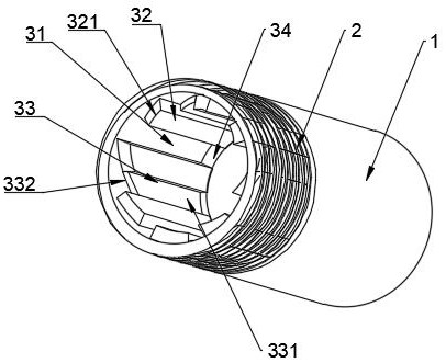
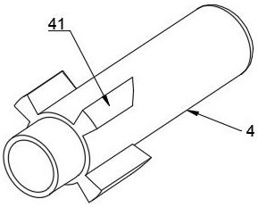
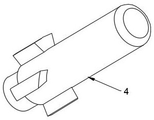
[0029] Such as Figure 1 to Figure 7 As shown, this embodiment provides an assembled wall sleeve, including an inner wall and an outer wall, one end of the outer wall is a thread 2, and the other end is a smooth curved surface 1; the inner wall at one end of the thread 2 is uniformly arranged with four connecting parts along the circumferential direction 3. Each connecting part 3 includes a first groove 31, a stopper 32 and a connecting block 33. A triangular groove 332 is formed between the end of the connecting block 33 and the end of the stopper 32, and the triangular groove 332 is clamped and fitted on the The first wedge-shaped column 41 of the movable tube 4; the end of the stopper 32 has a first inclined surface 321, and the first inclined surface 321 is slidably fitted with the first wedge-shaped column 41; the first groove 31 is slidably fitted with the second wedge-shaped Column 51.

[0030] Wherein, the connecting block 33 is provided with a second groove 331 , and...


PUM


Abstract

The invention belongs to the technical field of building decoration, and particularly relates to a sleeve for a fabricated wall surface. The sleeve comprises an inner wall and an outer wall, one end of the outer wall is a thread, and the other end of the outer wall is a smooth curved surface; four connecting parts are evenly distributed on the inner wall of one end of the thread in the circumferential direction, each connecting part comprises a first groove, a stop block and a connecting block, a triangular groove is formed between the end of each connecting block and the end of the corresponding stop block, and the triangular grooves are clamped and matched with first wedge-shaped columns of the movable pipe; first inclined surfaces are arranged at the end parts of the stop blocks and arein sliding fit with the first wedge-shaped columns; and the first grooves are in sliding fit with second wedge-shaped columns of a pressing head. Through the rotating motion of the first wedge-shapedcolumns, pressing dislocation among the pressing head, the movable pipe and the sleeve is achieved, the structure is simple, and operation is convenient.

Description

technical field [0001] The invention belongs to the technical field of architectural decoration, and in particular relates to an assembled wall sleeve. Background technique [0002] Medical equipment belts are generally installed on the bedside wall in the hospital ward, providing patients with various service facilities such as gas terminals, intercom call systems, data interfaces, lighting or air-conditioning switches, power switches, and bedside lamps. , which is an essential gas terminal control component for central oxygen supply and central suction systems. The existing medical equipment belt installed on the bedside wall of the hospital bed has caused great inconvenience to both the medical staff and the patients. When the connector is inserted, it will disturb or hit the patient, or the patient will block the connector on the equipment belt or accidentally get an electric shock, which will cause life-threatening; and if such an exposed equipment belt is installed in...

Claims


Application Information

Patent Timeline
Patent Type & Authority Applications(China)
IPC IPC(8): E04F13/22E04F13/23
CPCE04F13/0801
Inventor 丁欣欣丁泽成王文广周东珊操婷武鹏李鹏程
Owner ZHEJIANG YASHA DECORATION
Why Eureka
Try Eureka