Rapid forming die for machining parts with holes

A technology for forming molds and parts, which is applied in the field of rapid prototyping molds, can solve the problems of reducing production efficiency of parts, reducing part quality, easy shaking of molds, etc., and achieves the effect of improving production efficiency, improving molding quality, and good demoulding effect

Inactive Publication Date: 2021-03-05
辛集市儒意建筑装饰有限公司
View PDF0 Cites 2 Cited by
  • Summary
  • Abstract
  • Description
  • Claims
  • Application Information

AI Technical Summary

Problems solved by technology

[0003] The existing parts processing molds take a long time to form parts during use, and the demoulding speed is slow, which reduces the production efficiency of parts. In addition, during the injection process, the mold is easy to shake and has poor stability, which reduces the quality of parts

Method used


Image

  • Rapid forming die for machining parts with holes
  • Rapid forming die for machining parts with holes
  • Rapid forming die for machining parts with holes

Examples


Embodiment 1

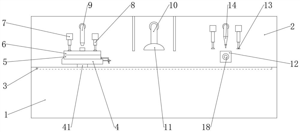
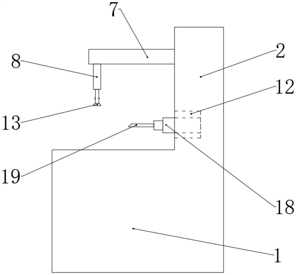
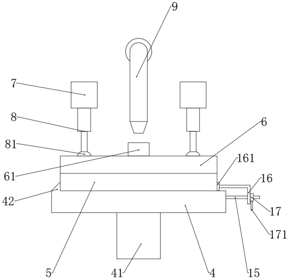
[0023] This embodiment 1 has introduced a kind of rapid prototyping mold for the processing of parts with holes, including base platform 1, vertical plate 2 and mold group, such as figure 1 and image 3 As shown, the vertical plate 2 is fixed on the top rear side of the base platform 1, the base plate 4 is slidably installed on the top front side of the base platform 1, and the slide rail 3 is provided on the top front side of the base platform 1 The middle of the bottom of the base plate 4 extends downwards and is fixed with an electric slider 41 that cooperates with the slide rail 3. The mold set includes a lower mold 5 and an upper mold 6, and a lower mold is arranged in the middle of the top of the lower mold 5. Cavity, the upper mold cavity is arranged in the middle of the bottom of the upper mold 6, the bottom of the material receiving pipe 61 communicates with the upper mold cavity, the lower mold 5 is placed on the top of the base plate 4, and the left side of the base...

Embodiment 2

[0025]This embodiment 2 introduces a rapid prototyping mold for processing parts with holes, including a base platform 1, a vertical plate 2 and a mold set, the vertical plate 2 is fixed on the rear side of the top of the base platform 1, A base plate 4 is slidably installed on the front side of the top of the base platform 1, and the mold set includes a lower mold 5 and an upper mold 6. The end of the base plate 4 near the vertical plate 2 is provided with a tunnel 43, and the lower mold set includes a lower mold 5 and an upper mold 6. A cylindrical rod 20 is movably installed at the bottom of the mold 5, and the bottom of the cylindrical rod 20 extends to the inside of the tunnel 43. A lower mold cavity is arranged in the middle of the top of the lower mold 5, and the bottom of the lower mold 5 is provided with a A through hole communicating with the cavity, the top of the base plate 4 is provided with a through hole one communicating with the channel 43, the through hole one...


PUM


Abstract

The invention relates to the technical field of dies, in particular to a rapid forming die for machining parts with holes. The die comprises a base platform, a vertical plate and a die set, the vertical plate is fixed to the rear side of the top of the base platform, a base plate is slidably mounted on the front side of the top of the base platform, and the die set comprises a lower die and an upper die. A clamping device for fixing the lower die is installed on the right side of the base plate, a hole channel is formed in the end, close to the vertical plate, of the base plate, a cylindricalrod is movably installed at the bottom of the lower die, a material receiving pipe is fixed to the top of the upper die, a cold air pipe is installed in the middle of the front end of the vertical plate, an air outlet is fixedly formed in the end, away from the vertical plate, of the cold air pipe, transverse rods are fixed to the left side and the right side of the front end of the vertical plate, first electric telescopic rods are installed at the bottoms of the other sides of the transverse rods, suction cups are installed at the bottoms of the first electric telescopic rods on the right side, a material injection pipe matched with the material receiving pipe is installed on the left side of the front end of the vertical plate, and an air gun pipe matched with the material receiving pipe is installed on the right side. The die is provided with three demolding mechanisms. The demolding effect is good.

Description

technical field [0001] The invention relates to the technical field of molds, in particular to a rapid prototyping mold used for processing parts with holes. Background technique [0002] Mold, various molds and tools used in industrial production for injection molding, blow molding, extrusion, die-casting or forging forming, smelting, stamping and other methods to obtain the required products. In short, a mold is a tool used to make shaped items, this tool is made up of various parts, and different molds are made up of different parts. It mainly realizes the processing of the shape of the article through the change of the physical state of the formed material. Known as the "Mother of Industry". [0003] The existing part processing molds take a long time to form parts during use, and the demoulding speed is slow, which reduces the production efficiency of the parts. In addition, during the injection process, the mold is easy to shake and has poor stability, which reduces ...

Claims


Application Information

Patent Timeline
Patent Type & Authority Applications(China)
IPC IPC(8): B29C33/30B29C35/16B29C45/40B29C45/46B29C45/64B29C45/73
CPCB29C33/305B29C35/16B29C45/4005B29C45/46B29C45/64B29C45/7337B29C2035/1658
Inventor 不公告发明人
Owner 辛集市儒意建筑装饰有限公司
Why Eureka
Try Eureka