
Laser processing apparatus

A technology of laser processing and laser beams, which is applied in the direction of fine working devices, metal processing, measuring devices, etc., and can solve problems such as interrupted processing

Pending Publication Date: 2021-03-05
DISCO CORP
View PDF2 Cites 0 Cited by
  • Summary
  • Abstract
  • Description
  • Claims
  • Application Information

AI Technical Summary

Problems solved by technology

However, these methods require interruption of processing, and it is difficult to measure the output while processing the workpiece.

Method used


Image

  • Laser processing apparatus
  • Laser processing apparatus
  • Laser processing apparatus

Examples


Embodiment Construction

[0022] Hereinafter, embodiments of the present invention will be described in detail with reference to the drawings. The present invention is not limited by the contents described in the following embodiments. In addition, the components described below include those that can be easily conceived by those skilled in the art, and those that are substantially the same. In addition, the structures described below can be combined appropriately. In addition, various omissions, substitutions, or changes in the structure can be made without departing from the scope of the present invention.

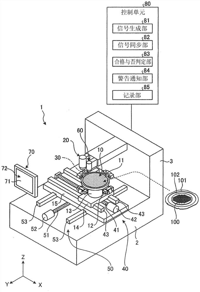
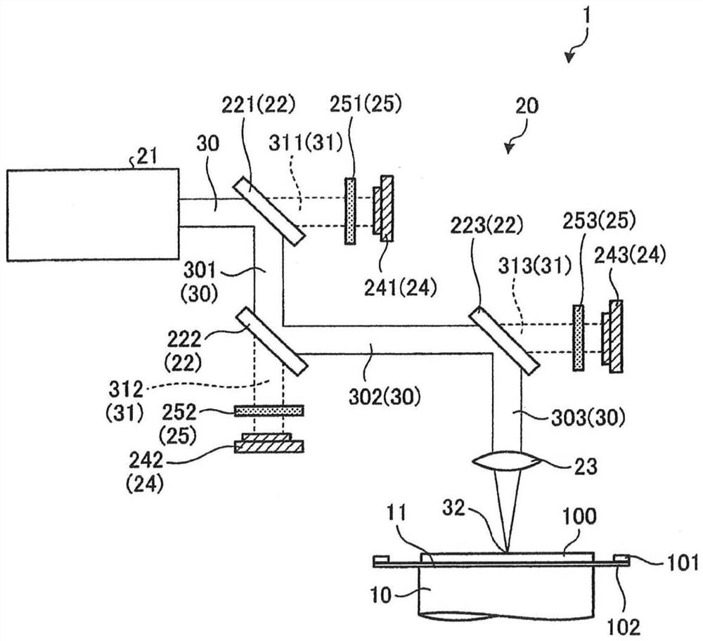
[0023] First, the structure of the laser processing apparatus 1 which concerns on embodiment of this invention is demonstrated based on drawing. figure 1 It is a perspective view which shows the structural example of the laser processing apparatus 1 of embodiment. figure 2 is schematically shown figure 1 A schematic diagram of the structure of the laser beam irradiation unit 20 of the laser ...


PUM


Abstract

The invention provides a laser processing apparatus capable of monitoring the output of a laser beam during processing without interrupting the processing while processing an object to be processed. Alaser beam irradiating unit of the laser processing apparatus includes a laser oscillator, a mirror configured to reflect a laser beam emitted from the laser oscillator and propagate the laser beam to a processing point, a power measuring unit configured to measure power of leakage light of the laser beam transmitted without being reflected by the mirror, and a condensing lens configured to condense the laser beam propagated by the mirror and irradiate a workpiece with the condensed laser beam. The control unit measures the power of the leakage light of the laser beam by the power measuring unit while irradiating the workpiece with the laser beam.

Description

technical field [0001] The present invention relates to a laser processing device. Background technique [0002] As a method of processing a workpiece such as a semiconductor wafer, a method of irradiating a laser beam having an absorptive wavelength to the front surface of the workpiece to form a processing groove and a method of irradiating a laser beam having a wavelength that is transparent to the workpiece are known. A method of converging and irradiating a laser beam inside a workpiece to form a modified layer as a division starting point (see Patent Documents 1 and 2). [0003] Patent Document 1: Japanese Patent Laid-Open No. 2003-320466 [0004] Patent Document 2: Japanese Patent Laid-Open No. 2002-192370 [0005] With respect to laser processing apparatuses that perform the above-mentioned laser processing, there is an increasing need to suppress poor division of workpieces and the like by monitoring changes in output of laser beams during processing. As a method...

Claims


Application Information

Patent Timeline
Patent Type & Authority Applications(China)
IPC IPC(8): B23K26/08B23K26/064B23K26/70B23K101/40
CPCB23K26/0884B23K26/0643B23K26/0648B23K26/702B23K2101/40G01J1/4257H01L21/6836B23K26/53B23K2103/56B23K26/707G05B19/406G05B2219/45041G05B2219/45154B23K26/0853B23K26/38B23K26/705B28D5/0058H01L21/67092G05B2219/34031B23K26/0665B23K26/032G01J1/44H01L21/67115H01L21/67253G05B19/4155H01L2221/68327B23K26/0622
Inventor 瓜生宏树三浦诚治朝日阳彦藤泽尚俊小林良树赤松秀典
Owner DISCO CORP
Learn More