Mitral valve device and use method

A mitral valve and delivery device technology, applied in the field of medical devices, can solve the problems of mitral valve interventional valve placement, affecting blood flow, valve compression, etc., to reduce blood flow obstruction, prolong use time, reduce valve The effect of leaking

Pending Publication Date: 2021-03-05
QICHEN (SHANGHAI) MEDICAL EQUIP CO LTD
View PDF1 Cites 3 Cited by
  • Summary
  • Abstract
  • Description
  • Claims
  • Application Information

AI Technical Summary

Problems solved by technology

Although this technical solution can solve some technical problems in the manufacture of atrioventricular valve stents, due to the particularity of the mitral valve structure, it is difficult to insert the mitral valve interventional valve and it is not easy to fix after insertion, and there are still many problems

Method used


Image

  • Mitral valve device and use method
  • Mitral valve device and use method
  • Mitral valve device and use method

Examples


Embodiment 1

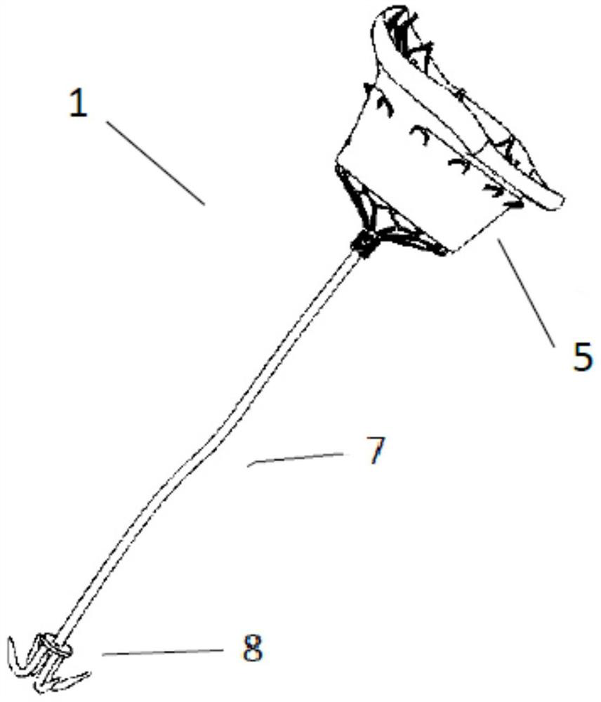
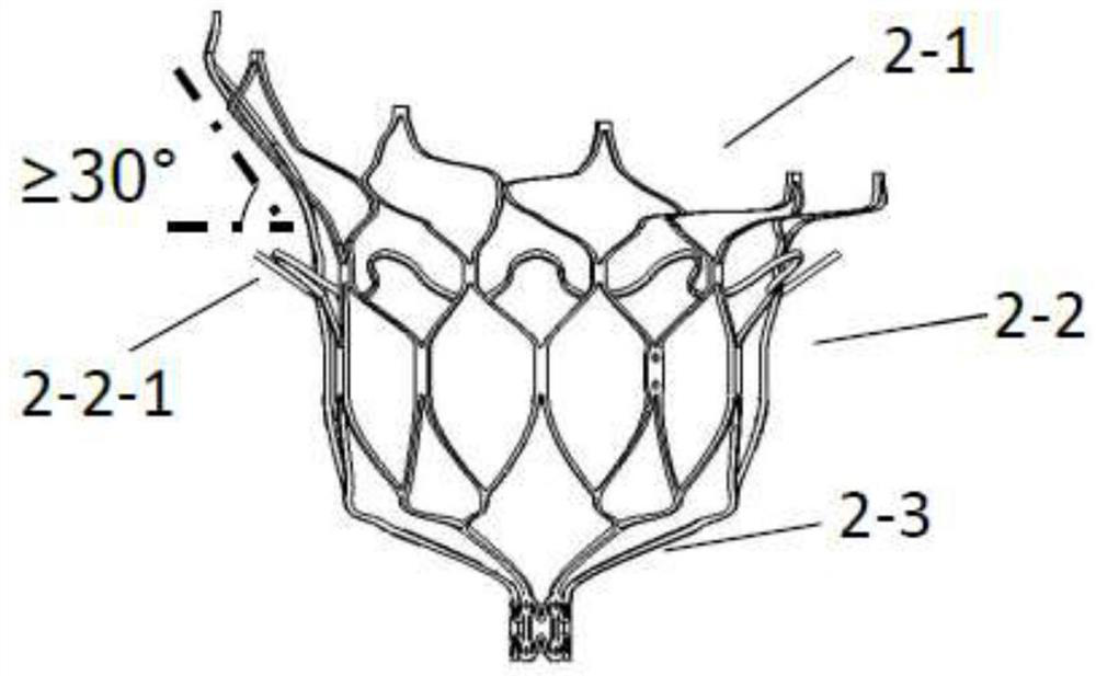
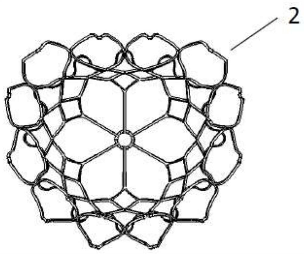
[0064] Such as Figure 1-13 As shown, the mitral valve device 1 of the present embodiment includes a stent and a leaflet 6. The stent includes an outer stent 2 and an inner stent 3. The outer stent 2 protects the inner stent 3 and limits the valve Movement in the heart after release; the surfaces of the outer stent 2 and the inner stent 3 are attached with a suture film 5, and the outer stent 2 and the inner stent 3 are sutured and flexibly connected through the suture film 5; the outer stent 2 includes an upper end The expansion frame 2-1 is used to be placed at the atrium end, and the barrel-shaped frame 2-2 at the lower end is used to extend from the atrial end to the ventricle through the annulus to undertake the upper end; the expansion frame 2-1 has a concave expansion shape, The concave structure can fit the surface of the aorta, and is suitable for the shape of the atrial end close to the annulus, and one side of the expanded frame 2-1 has a highly convex atrial wall f...

Embodiment 2

[0081] The difference between the method of using the mitral valve device of this example and the embodiment is that:

[0082] Such as Figure 14 shown, including the following steps:

[0083] S1, storing the mitral valve device in the lumen of the delivery device, and entering the left atrium through the delivery device through blood vessels or the right atrium;

[0084] S2, reaching the apex of the heart, releasing the anchoring piece through the delivery device and anchoring it to the apex of the heart;

[0085] S3, releasing the drawstring, adjusting the length of the drawstring and tightening the drawstring;

[0086] S4, sequentially releasing the tightening structure, the barrel frame, and the expanding frame to the target position;

[0087] S5, evacuate the conveying device.

[0088] Compared with Embodiment 1, the conveying path of the conveying device is not limited, and the device is more universal.

[0089] For other structures, refer to Embodiment 1.

Embodiment 3

[0091] The difference between the mitral valve device of this embodiment and Embodiment 1 is:

[0092] Such as Figure 15 As shown, the constriction opening of the tightening structure of this embodiment is small, and the incomplete contraction is performed. Compared with the first embodiment, the toughness of the device can be improved, and the blood flow resistance can be further reduced.

[0093] For other structures, refer to Embodiment 1.


PUM

PropertyMeasurementUnit
Wall thicknessaaaaaaaaaa
Diameteraaaaaaaaaa
Heightaaaaaaaaaa

Abstract

The invention relates to the technical field of medical instruments, and particularly relates to a mitral valve device and a use method. The mitral valve device comprises a support and a valve leaflet, wherein the support comprises an outer support and an inner support and is flexibly connected with the outer support through a suture membrane in a suture mode; the outer support comprises an outerexpansion frame and a lower barrel-shaped frame; the upper end of the outer expansion frame is used for being placed at the atrium end; the lower barrel-shaped frame is connected with the upper end and used for extending from the atrium end to the atrium through a valve ring; a highly-protruding atrium wall fitting face is arranged on one side of the outer expansion frame; a plurality of protruding structures are arranged at the position, close to the valve ring, of the peripheral side of the barrel-shaped frame; the inner support is cylindrical, and the valve leaflet is sutured in the inner support through a clamping piece; and a tightening structure is arranged at the tail end of the support and connected with an anchoring part through a pull rope. According to the mitral valve device and the use method, the mitral valve device can better adapt to the anatomical structure of the heart through the double-layer support structure and the asymmetric outer support, the influence of heartmovement on the inner support and the valve leaflet is reduced, the device plays the efficacy, and the service life of the device is prolonged.

Description

technical field [0001] The invention relates to the technical field of medical devices, in particular to a mitral valve device and a use method. Background technique [0002] The mitral valve is located between the left atrium and the left ventricle, like a one-way valve, ensuring blood flows from the left atrium to the left ventricle and through a certain flow. The mitral valve complex is a functionally and anatomically complex group of devices generally considered to include the annulus, leaflets, chordae, and papillary muscles. The function of the mitral valve depends on the integrity of its physiological structure. When the normal mitral valve is closed, the two valve leaflets are in the same plane and close together, which can completely block the backflow of ventricular blood flow. To achieve this effect, it is required that the size of the mitral annulus is appropriate, the leaflet structure is intact, the papillary muscle contracts and pulls the chordae to support ...

Claims


Application Information

Patent Timeline
IPC IPC(8): A61F2/24
CPCA61F2/24A61F2/2418A61F2/2442A61F2/2466A61F2220/0016
Inventor 梁玉晨
Owner QICHEN (SHANGHAI) MEDICAL EQUIP CO LTD
Why Eureka
Try Eureka