
Intelligent trailing edge dimming device based on MOSFET

A rear-edge dimming and intelligent technology, applied in lighting devices, light sources, electric light sources, etc., can solve problems such as poor EMC electromagnetic compatibility

Active Publication Date: 2021-03-02
广州河东科技有限公司
View PDF7 Cites 0 Cited by
  • Summary
  • Abstract
  • Description
  • Claims
  • Application Information

AI Technical Summary

Problems solved by technology

[0006] The embodiment of the present application provides a MOSFET-based intelligent trailing edge dimming device, which solves the problem of poor EMC electromagnetic compatibility performance of the traditional trailing edge phase-cut control dimming technology circuit, so as to improve the reliability of the dimming device

Method used


Image

  • Intelligent trailing edge dimming device based on MOSFET
  • Intelligent trailing edge dimming device based on MOSFET

Examples


Embodiment 1

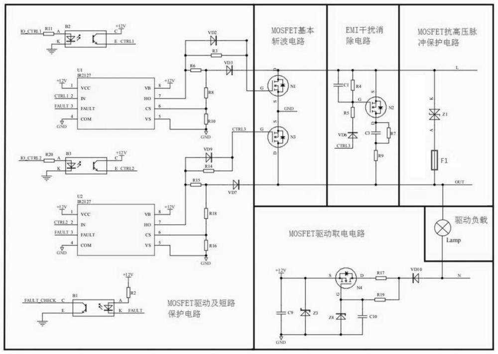
[0025] figure 2 It is a schematic circuit diagram of a MOSFET-based intelligent trailing edge dimming device provided in an embodiment of the present application. Such as figure 2 As shown, a MOSFET-based intelligent trailing edge dimming device includes a MOSFET basic chopper circuit, a MOSFET drive and short-circuit protection circuit, a MOSFET drive power-taking circuit, a MOSFET anti-high voltage pulse protection circuit, and an EMI interference elimination circuit;

[0026] The MOSFET basic chopping circuit is respectively connected with the MOSFET driving and short-circuit protection circuit, the EMI interference elimination circuit, and the MOSFET anti-high voltage pulse protection circuit;

[0027] The EMI interference elimination circuit is connected with the MOSFET anti-high voltage pulse protection circuit;

[0028] The MOSFET anti-high voltage pulse protection circuit is connected to the driving load;

[0029] The MOSFET drive and short circuit protection circ...


PUM


Abstract

The embodiment of the invention discloses an intelligent trailing edge dimming device based on an MOSFET. The intelligent trailing edge dimming device comprises an MOSFET basic chopper circuit, an MOSFET driving and short-circuit protection circuit, an MOSFET driving power-taking circuit, an MOSFET anti-high-voltage pulse protection circuit and an EMI interference elimination circuit. The MOSFET basic chopper circuit is connected with the MOSFET driving and short-circuit protection circuit, the EMI interference elimination circuit and the MOSFET high-voltage pulse resistance protection circuit; the EMI interference elimination circuit is connected with the MOSFET anti-high-voltage pulse protection circuit; the MOSFET anti-high-voltage pulse protection circuit is connected with a driving load; the MOSFET driving and short-circuit protection circuit is connected with the MOSFET driving power-taking circuit; and the MOSFET driving power-taking circuit is connected with a driving load. Through the above technical means, a plurality of semiconductor devices form the intelligent trailing edge dimming device, miniaturization of equipment is achieved, EMC electromagnetic compatibility requirements are met, pure resistive loads and capacitive loads are compatible, and most market requirements can be met. A plurality of protection circuits are configured, so that the stability of the MOSFET basic chopper circuit is improved, and the reliability of the intelligent trailing edge dimming device is improved.

Description

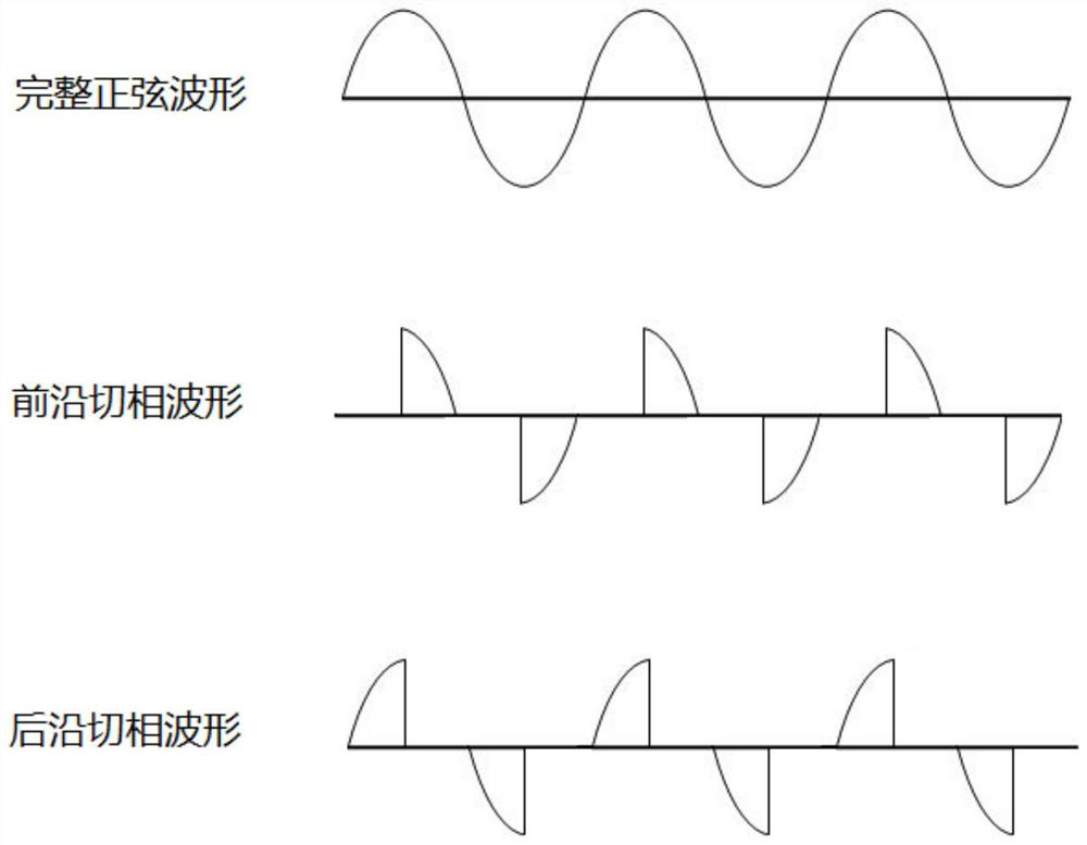
technical field [0001] The embodiment of the present application relates to the technical field of phase control dimming, and in particular to an intelligent trailing edge dimming device based on the . Background technique [0002] Such as figure 1 As shown, the phase control dimming technology includes leading-edge phase-cut dimming technology and trailing-edge phase-cut dimming technology. It uses power electronic semiconductor devices to control the sinusoidal AC power supply of the lighting system, and adjusts the guide of each half-wave of the AC. The sinusoidal waveform can be changed by changing the angle of rotation, thereby changing the effective value of the AC current to achieve the purpose of dimming. [0003] Leading-edge phase-cutting control dimming is usually implemented by a silicon controlled rectifier circuit. A trigger pulse is applied to the silicon controlled rectifier after a period of time after the half sine wave crosses zero to trigger the conducti...

Claims


Application Information

Patent Timeline
IPC IPC(8): H05B45/36H05B45/50H05B45/3725H05B45/34H05B39/04
CPCH05B45/36H05B45/50H05B45/3725H05B45/34H05B39/04Y02B20/40
Inventor 陈考敏薛柯利曾义杜其昌
Owner 广州河东科技有限公司
Learn More