A panoramic monitor with adjustable field of view

A monitor and panorama technology, applied in the field of panorama monitors, can solve the problems of non-adjustable field of view of panorama monitors, limit shrinkage of panorama monitor applications, etc., and achieve the effect of improving adjustability and expanding applications

Active Publication Date: 2022-03-04
ZHUHAI DAHENGQIN TECH DEV CO LTD
View PDF7 Cites 0 Cited by
  • Summary
  • Abstract
  • Description
  • Claims
  • Application Information

AI Technical Summary

Problems solved by technology

[0004] In the panoramic imaging technology of multi-camera splicing, since the lenses are usually fixed, the field of view of the panoramic monitor in the vertical direction cannot be adjusted, which limits the application of the panoramic monitor.

Method used


Image

  • A panoramic monitor with adjustable field of view
  • A panoramic monitor with adjustable field of view
  • A panoramic monitor with adjustable field of view

Examples


Embodiment 1

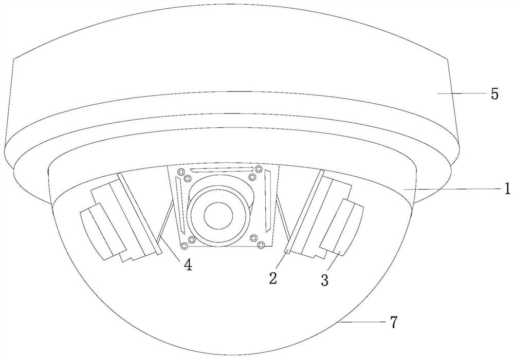
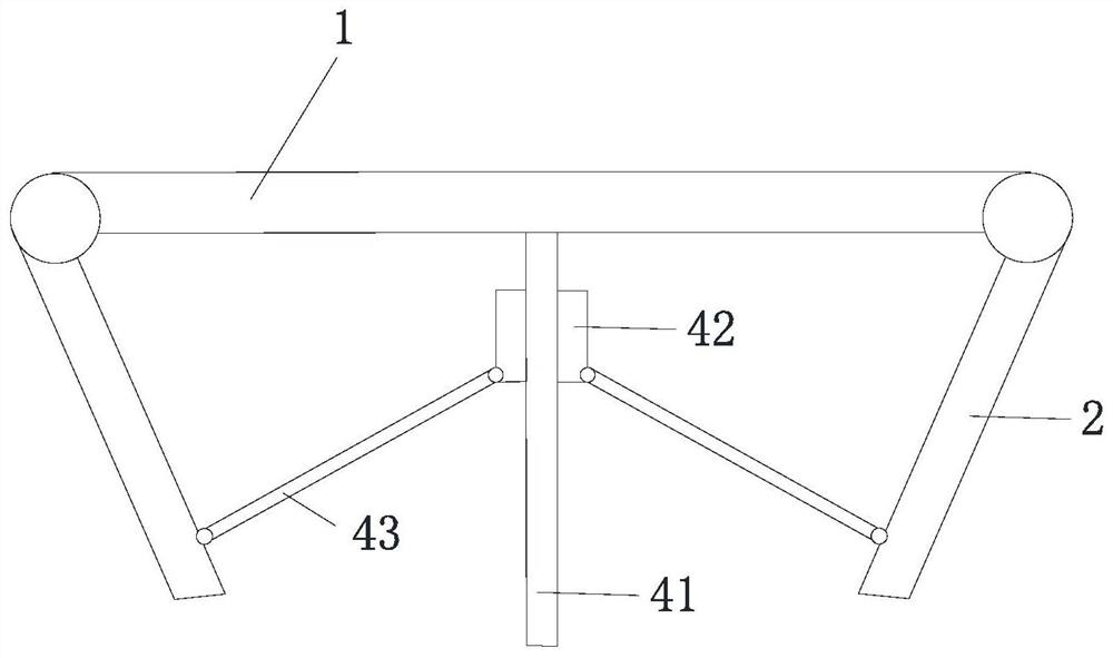
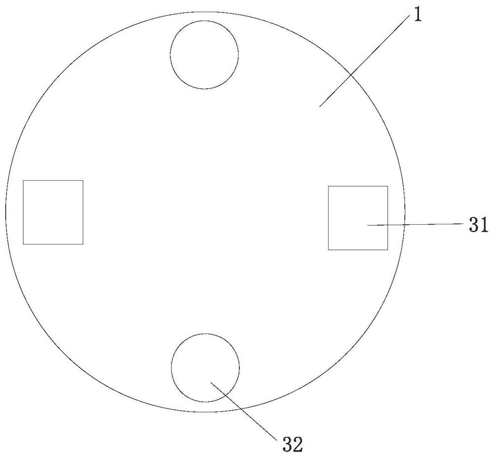
[0046] combine Figure 1-4 , this embodiment relates to a panoramic monitor with an adjustable field of view, including a substrate 1 , a mounting plate 2 , a camera 3 and a first drive assembly 4 .

[0047] Wherein, the base plate 1 is arranged in a horizontal direction, and at least two mounting plates 2 are provided. One end of the mounting plate 2 is hinged to the base plate 1, and the other end is a free end, and the free end of the mounting plate 2 can rotate in the vertical direction around the hinge shaft. The camera 3 is installed on the substrate 1, and the camera 3 is arranged in one-to-one correspondence with the mounting plate 2, the first driving assembly 4 is installed on the substrate 1, and the output end of the first driving assembly 4 is assembled with the free end of the mounting plate 2, The first driving assembly 4 is used to drive the free end of the mounting plate 2 to move toward or away from the substrate 1 .

[0048] To realize the panoramic monitor...


PUM


Abstract

The present invention relates to the technical field of monitoring equipment, in particular to a panoramic monitor with adjustable field of view, comprising: a base plate arranged in a horizontal direction; at least two mounting plates, one end of which is hinged to the base plate, and the other end is a free end, The free end of the mounting plate can rotate in the vertical direction around the hinge shaft; the camera is mounted on the mounting plate and corresponds to the mounting plate one by one; Assembly, used to drive the free end of the mounting plate to move towards or away from the base plate. By arranging the mounting plate and the first drive assembly, and installing the camera on the mounting plate, it is only necessary to drive the free end of the mounting plate to rotate through the first drive assembly to realize the adjustment of the camera’s orientation angle, thereby adjusting the panoramic monitoring The role of the field of view of the monitor in the vertical direction expands the applicable scenarios of the panoramic monitor.

Description

technical field [0001] The invention relates to the technical field of monitoring equipment, in particular to a panoramic monitor with an adjustable field of view. Background technique [0002] Panoramic imaging technology uses a special imaging device to obtain a hemispherical field of view greater than 180 degrees or a 360-degree spherical field of view in the horizontal or vertical direction. The implementation methods of panoramic imaging system mainly include fisheye lens, multi-camera splicing and catadioptric type. [0003] Among them, multi-camera splicing is to set multiple lenses in the horizontal direction, each lens shoots at a predetermined angle, and then splice the pictures captured by each lens to form a complete 360° field of view in the horizontal direction. [0004] In the panoramic imaging technology of multi-camera splicing, since the lenses are usually fixed, the field of view of the panoramic monitor in the vertical direction cannot be adjusted, which...

Claims


Application Information

Patent Timeline
Patent Type & Authority Patents(China)
IPC IPC(8): H04N7/18H04N5/225H04N5/232
CPCH04N7/181H04N23/50H04N23/66H04N23/698
Inventor 邓练兵余大勇方文佳
Owner ZHUHAI DAHENGQIN TECH DEV CO LTD
Why Eureka
Try Eureka