
Steel bar binding device for construction site

A technology for tying steel bars and construction sites, which is applied in the processing of building materials, construction, building construction, etc., and can solve the problems of low work efficiency, large workload, and cumbersome operation process.

Inactive Publication Date: 2021-03-02
江苏五环建工集团有限公司
View PDF4 Cites 0 Cited by
  • Summary
  • Abstract
  • Description
  • Claims
  • Application Information

AI Technical Summary

Problems solved by technology

Since the binding is completely performed manually, the operation process is cumbersome, the work efficiency is low, and the workload is large

Method used


Image

  • Steel bar binding device for construction site

Examples


Embodiment

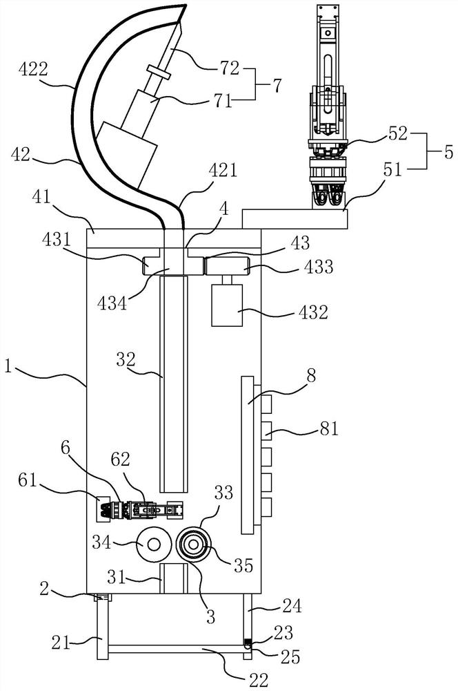
[0037] A steel bar binding device for construction sites, such as figure 1As shown, it includes: installation case 1, the rear end of the installation case 1 is provided with an upper wire mechanism 2 for installing the wire reel; a wire feeding mechanism 3 is arranged in the installation case 1 for driving the wire feeding forward Carried on the front end of the installation casing 1 for guiding the binding wire through the guide mechanism 4 to be bound, the guide mechanism 4 includes: a mounting seat 41 that is rotatably assembled on the installation casing 1, fixed on the mounting seat 41 and connected with the installation The arc-shaped guide tube 42 connected to the casing 1 and the rotation drive assembly 43 used to drive the rotation of the mounting base 41; the clamping mechanism 5 fixed on the mounting base 41 and arranged opposite to the arc-shaped guide tube 42, Between the curved guide pipe 42 is formed a port for the passage of steel bars to be bound; the locking...


PUM


Abstract

The invention relates to a steel bar binding device for a construction site. The steel bar binding device comprises a mounting machine shell, a wire conveying mechanism, a guide mechanism, a clampingmechanism, a locking mechanism, a wire cutting mechanism and a control circuit board, wherein a wire feeding mechanism is arranged at the rear end of the mounting machine shell; the guide mechanism comprises a mounting seat which is rotatably assembled on the mounting machine shell, an arc-shaped guide pipe and a rotary driving assembly; a through opening is formed between the clamping mechanism and the arc-shaped guide pipe; and the control circuit board is arranged in the mounting machine shell and is connected with a control key. According to the steel bar binding device, the wire feeding mechanism, the wire conveying mechanism, the guide mechanism, the clamping mechanism, the locking mechanism and the wire cutting mechanism are arranged, the rotary driving assembly drives the mountingseat to rotate, a binding wire can be naturally wound and bound in the rotating process, so that binding of steel bars is realized; and finally, the binding wire is cut off from the front end of the arc-shaped guide pipe through the wire cutting mechanism, so that automatic binding of the steel bars is realized, the binding efficiency is improved, and the manual workload is reduced.

Description

technical field [0001] The invention relates to the technical field of building construction aids, in particular to a steel bar binding device used on a construction site. Background technique [0002] Steel bars are the "heart" that supports the entire building. In the early stage of building construction, it is necessary to use steel bar tie wires to bind the intersections of vertical and horizontal steel bars to facilitate more convenient and safe construction. When tying, the worker pulls out a binding wire with his right hand, bends the bending part 90 degrees, then passes the bent part through the bottom of the steel bar binding point with his left hand, hooks the binding wire buckle with the steel bar binding hook, and presses the index finger on the hook The front part is close to the open end of the binding wire, and it is rotated clockwise two or three times to complete the binding of a node. Since the binding is completely performed manually, the operation proces...

Claims


Application Information

Patent Timeline
Patent Type & Authority Applications(China)
IPC IPC(8): E04G21/12
CPCE04G21/123
Inventor 张建华李健黄安保
Owner 江苏五环建工集团有限公司
Learn More