Swing sliding type flapping rotor device

A flapping-rotor and sliding-type technology, applied in the field of aircraft, can solve the problems of strong air disturbance force and low ascent efficiency of flapping-rotor aircraft, and achieve the effects of strengthening the interference intensity, improving the disturbance intensity and improving the stability.

Inactive Publication Date: 2021-03-02
GUANGDONG GUOSHIJIAN TECH DEV CO LTD
View PDF0 Cites 0 Cited by
  • Summary
  • Abstract
  • Description
  • Claims
  • Application Information

AI Technical Summary

Problems solved by technology

[0002] The flapping rotorcraft is a new type of aircraft that imitates the flight of birds. It has the advantages of vertical lift and hovering in the air of both rotorcraft and helicopters. The core device of the flapping rotorcraft is the flapping rotor set on both sides of the fuselage. device, but the flapping rotor device in the prior art will cancel part of the lift force in the process of performing up and down movements, and the existing flapping rotor is in the process of flapping the air, the position of the rotor on the flapping rotor is fixed, resulting in The disturbance to the air is strong, so the efficiency of the flapping rotorcraft's ascent is low

Method used


Image

  • Swing sliding type flapping rotor device
  • Swing sliding type flapping rotor device
  • Swing sliding type flapping rotor device

Examples


Embodiment 1

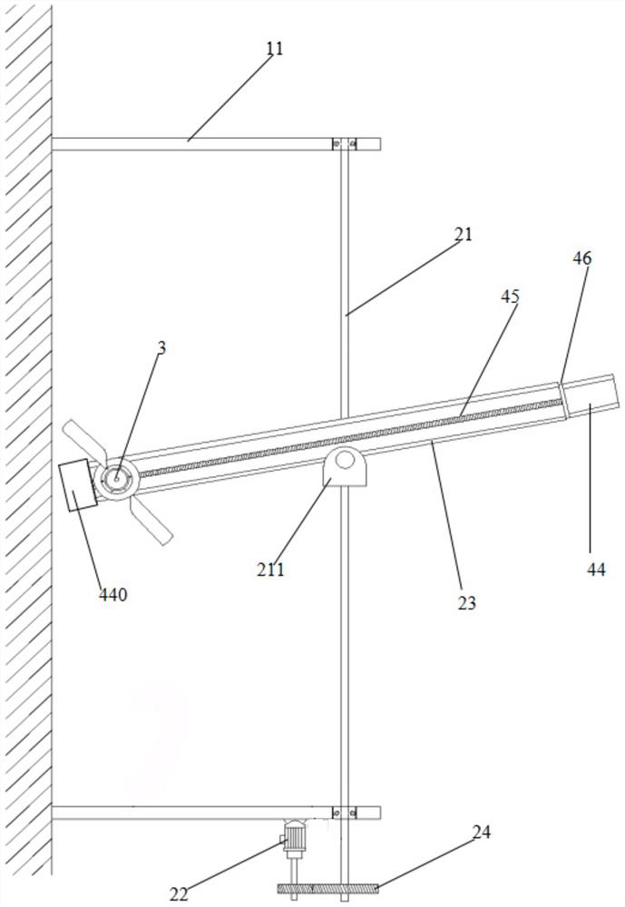
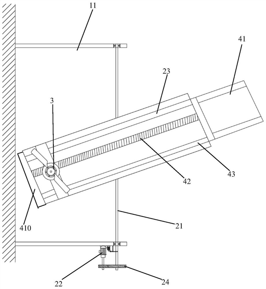
[0074] The embodiment of the present invention discloses a swinging and sliding flapping rotor device, which is symmetrically arranged on both sides of the fuselage, including: a front bracket 11, a rear bracket 12, a main shaft 21, a main shaft motor 22, a transmission gear set 24, a swing arm 23, Rotor 3, linear drive and controller;

[0075] The front support 11 and the rear support 12 are all vertically fixed on the side of the fuselage, and are parallel to each other and arranged at intervals:

[0076] The main shaft 21 is arranged between the front bracket 11 and the rear bracket 12, its axial centerline is parallel to the axial centerline of the fuselage, and its two ends are connected to the front bracket 11 and the rear bracket 12 through bearing rotation;

[0077] The main shaft motor 22 is fixed on the front bracket 11 or the rear bracket 12, and is connected to the main shaft 21 through the transmission gear set 24, and is electrically connected to the controller, ...

Embodiment 2

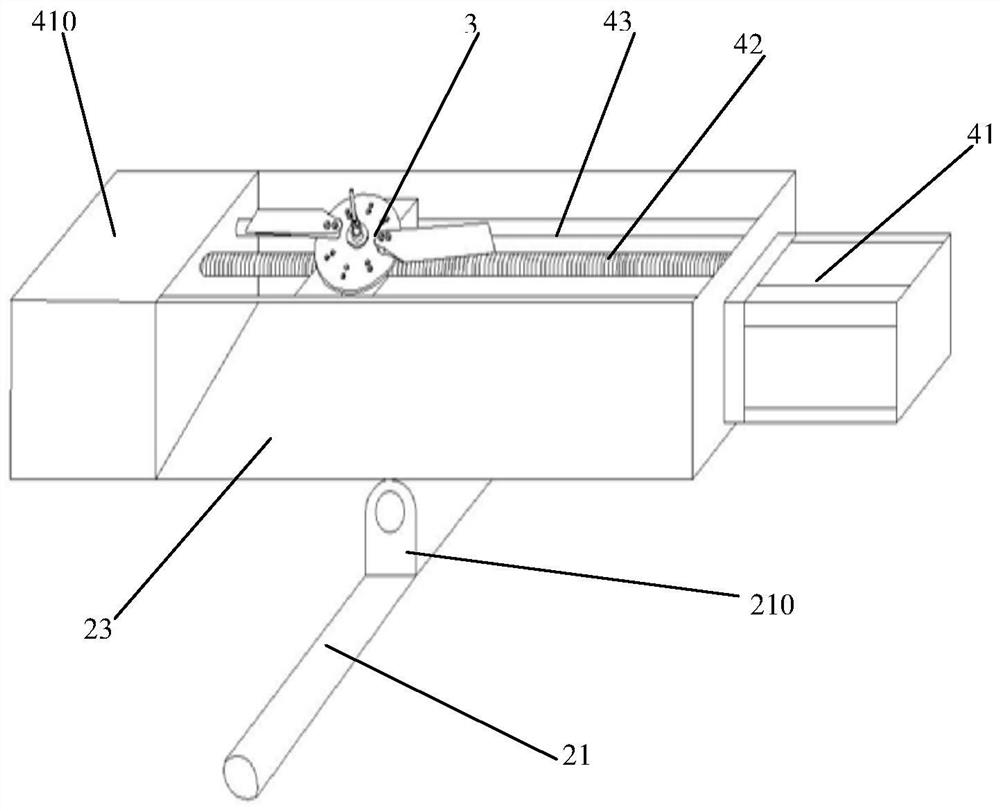
[0091] On the basis of Embodiment 1, there are multiple swing frames and first mounting bases 210, and the swing frames are connected to the first mounting bases 210 in one-to-one rotation through rotating shafts, and there is a phase difference among the multiple swing frames.

[0092] The present invention has a plurality of swinging frames, so that the interference intensity to the air can be strengthened, and the efficiency of the lift generation of the present invention can be further improved.

Embodiment 3

[0094] The difference from Embodiment 1 is that the swing arm 23 is a swing rod, the main shaft 21 is fixed with a second mount 211, and the center of the bottom of the swing frame is connected to the second mount 211 through a rotating shaft;

[0095] There are multiple swing rods and the second mounting base 211 , and the swing rods are connected to the second mounting bases 211 in one-to-one rotation through the rotating shaft, and there is a phase difference among the multiple swing rods.

[0096] The linear drive device includes a second motor 44, a second screw 45 and two vertical plates 46;

[0097] The second motor 44 is fixed on one end of the fork, and is electrically connected with the controller;

[0098] Two vertical plates 46 are parallel to each other, and are respectively fixed on the two ends of the fork;

[0099] The second lead screw 45 is arranged between the two vertical plates 46, and the two ends of the screw rod are rotatably connected with the vertica...


PUM


Abstract

The invention discloses a swing sliding type flapping rotor device, which is characterized in that main shafts are arranged on two sides of a fuselage through flapping rotor wing brackets and are rotationally connected with the flapping rotor wing brackets through bearings, and the axial center lines of the main shafts are parallel to the axial center line of the fuselage; the center of the bottomof the swing arm is rotationally connected to the main shaft through a rotating shaft, and meanwhile the linear driving device is installed on the swing arm and electrically connected with the controller. Rotor types of the rotors are symmetrical biconvex wings, a center hole is formed in the center of the rotary disc, a center shaft penetrates through the center hole and is rotationally connected with the rotary disc through a bearing, meanwhile, the center shaft is connected to a linear driving device, the linear driving device drives the center shaft to slide on the swing arm in a reciprocating mode, and the swing arm swings relative to the main shaft through a rotary shaft. The invention discloses the swing sliding type flapping rotor device. The efficiency and the size of lift forcegeneration are improved.

Description

technical field [0001] The invention relates to the technical field of aircraft, and more specifically relates to a swinging and sliding flapping rotor device. Background technique [0002] The flapping rotorcraft is a new type of aircraft that imitates the flight of birds. It has the advantages of vertical lift and hovering in the air of both rotorcraft and helicopters. The core device of the flapping rotorcraft is the flapping rotor set on both sides of the fuselage. device, but the flapping rotor device in the prior art will cancel part of the lift force in the process of performing up and down movements, and the existing flapping rotor is in the process of flapping the air, the position of the rotor on the flapping rotor is fixed, resulting in The disturbance to the air is strong, so the efficiency of the flapping rotorcraft's ascent is low. Contents of the invention [0003] The present invention aims to solve one of the above-mentioned technical problems in the prio...

Claims


Application Information

Patent Timeline
IPC IPC(8): B64C27/32B64C33/02B64C27/22B64D27/24B64D35/00B64D35/02
CPCB64C27/32B64C33/02B64C27/22B64D27/24B64D35/00B64D35/02Y02T50/60
Inventor 王志成
Owner GUANGDONG GUOSHIJIAN TECH DEV CO LTD
Why Eureka
Try Eureka