
Perforating mechanism for industrial aluminum profile machining

A technology of aluminum profile processing and perforating mechanism, which is applied in the direction of metal processing machinery parts, metal processing equipment, manufacturing tools, etc., can solve the problems of reducing the cleanliness of the working environment, inconvenient collection of cutting fluid, scattered splashes, etc., to improve the cleaning effect and Work efficiency, convenient cleaning work, and the effect of improving cleanliness

Inactive Publication Date: 2021-03-02
SUZHOU MULTITECH AUTOMATION EQUIP CO LTD
View PDF0 Cites 1 Cited by
  • Summary
  • Abstract
  • Description
  • Claims
  • Application Information

AI Technical Summary

Problems solved by technology

However, after the cutting fluid is in contact with the drill bit and the aluminum profile, the cutting fluid and the cutting debris are mixed, and then flow to the bottom plate of the punching machine, and flow around along the bottom plate; The mixture will be scattered and splashed, reducing the cleanliness of the working environment, and the outflowing cutting fluid is inconvenient to collect, which will cause a waste of resources

Method used


Image

  • Perforating mechanism for industrial aluminum profile machining
  • Perforating mechanism for industrial aluminum profile machining
  • Perforating mechanism for industrial aluminum profile machining

Examples


Embodiment Construction

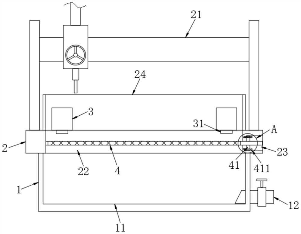
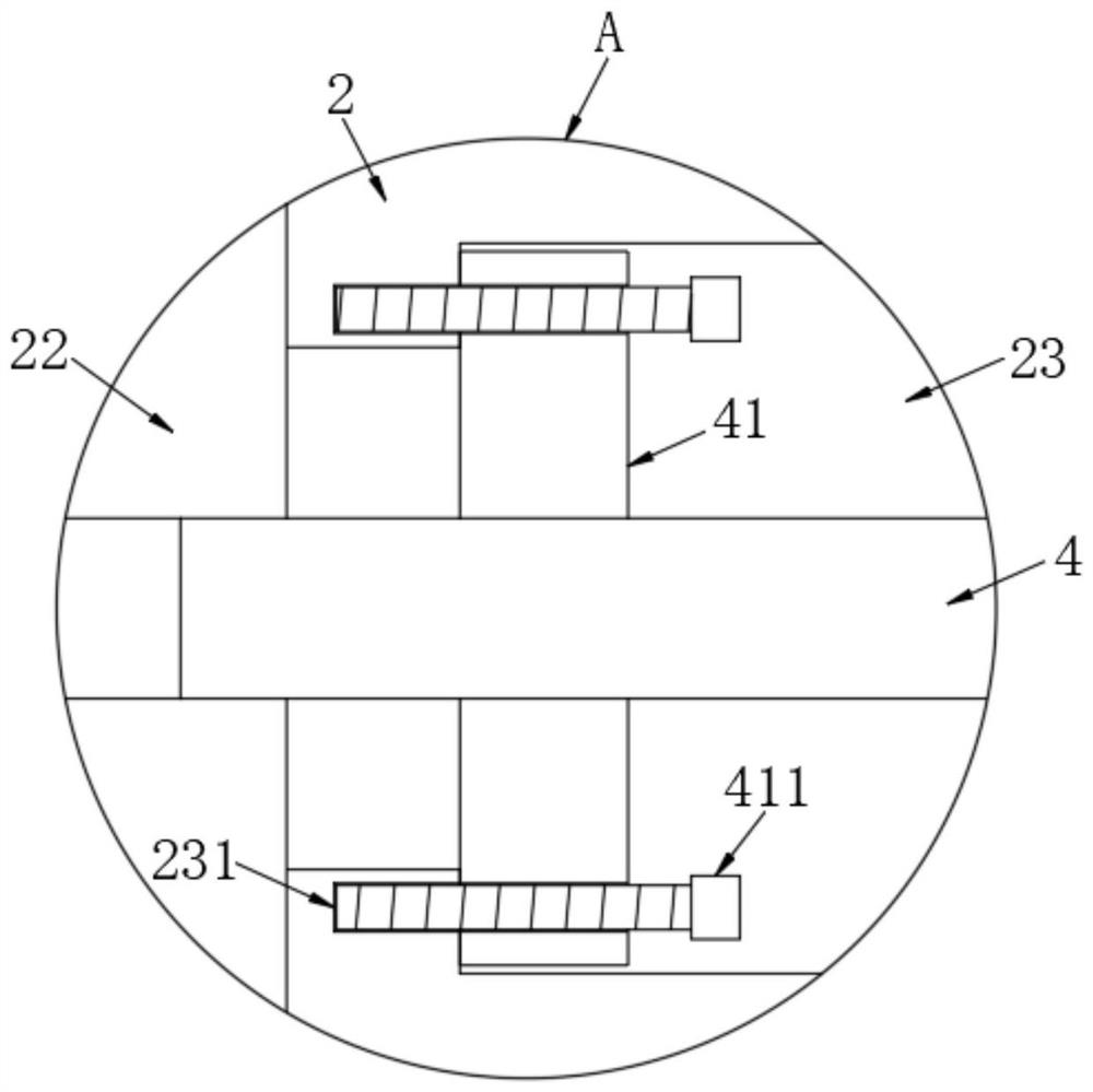
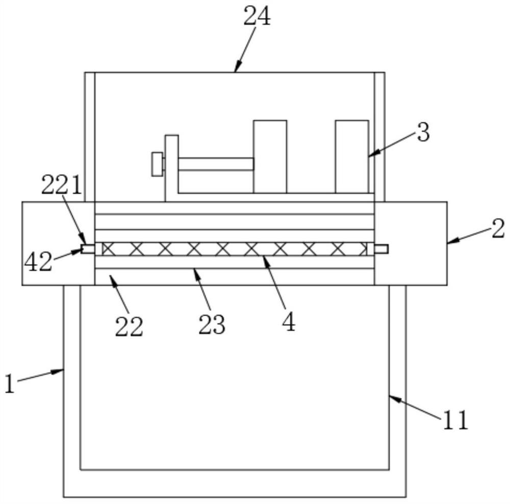
[0034] see Figure 1~4 , this specific embodiment describes in detail a piercing mechanism for industrial aluminum profile processing. The perforating mechanism includes a base 1 and a top plate 2 fixedly installed on the top of the base 1, and the base 1 and the top plate 2 are combined to form a workbench. The upper surface of the top plate 2 is positioned with a perforating assembly 21. This perforating assembly is a conventional perforating assembly in the art, generally including a gantry, which can be positioned and slid along the beam of the gantry and a perforating drill bit that can be positioned and moved up and down in the vertical direction. , its specific structure will not be repeated in this application and specific embodiments.

[0035] In the present application, the upper surface of the top plate 2 of the perforation mechanism is fixedly connected with a stop frame 24 arranged along the length direction of the top plate. The stop frame can be set as a stop p...


PUM


Abstract

The invention discloses a perforating mechanism for industrial aluminum profile machining, and belongs to the technical field of equipment for aluminum profile machining. The perforating mechanism comprises a base and a top plate fixedly installed at the top of the base, a perforating assembly is fixedly connected to the top of the top plate, a blocking frame arranged in the length direction of the top plate is fixedly connected to the upper surface of the top plate, a through groove which is formed in the length direction of the top plate and penetrates through the upper part and the lower part of the top plate is formed in the top plate, and a filter plate is detachably connected into the through groove in a positioning mode; clamps which are symmetrically distributed are fixedly connected to the top of the inner wall of the through groove and located above the filter plate, and the clamps and the through groove are located on the same side of the blocking frame; and a collecting cavity located below the through groove is formed in the base. During working, sprayed cutting fluid can directly enter the through groove downwards, mixed chippings in the cutting fluid can be filteredout through the filter plate, the filtered cutting fluid enters the collecting cavity downwards, it is guaranteed that the top plate and the working environment are clean and tidy, and the cutting fluid and the chippings can be recycled conveniently, so that recycling is convenient.

Description

technical field [0001] The invention relates to a punching mechanism, in particular to a punching mechanism for processing industrial aluminum profiles, and belongs to the technical field of equipment for processing aluminum profiles. Background technique [0002] Aluminum profile is an alloy material with aluminum as the main component. It is obtained by extruding aluminum rods with different cross-sectional shapes after hot melting. According to the different proportions of alloys added, the mechanical properties and application fields of the produced aluminum profiles are also different. Among them, industrial aluminum profiles refer to all aluminum profiles except for building doors and windows, curtain walls, interior and exterior decoration, and aluminum profiles for building structures. When processing industrial aluminum profiles, it is often necessary to perforate the aluminum profiles for subsequent processing or use. [0003] At present, the punching machine is g...

Claims


Application Information

Patent Timeline
IPC IPC(8): B23B41/00B23Q11/10B23Q11/00
CPCB23B41/00B23Q11/10B23Q11/1069
Inventor 陶进
Owner SUZHOU MULTITECH AUTOMATION EQUIP CO LTD
Learn More