
catheter balloon

A catheter balloon and balloon technology, applied in catheters, balloon-shaped catheters, etc., can solve the problems of limited inflatable capacity, inability to obtain, and difficulty in the process of balloon delivery, and achieve the effects of increasing inflation volume and ingenious design.

Active Publication Date: 2021-04-16
BEIJING TAIJIE WEIYE TECH
View PDF5 Cites 1 Cited by
  • Summary
  • Abstract
  • Description
  • Claims
  • Application Information

AI Technical Summary

Problems solved by technology

[0004] Knownly, the balloon is made of elastic material, which is elastically deformed under the action of fluid pressure, and then expands. However, due to the influence of the elastic deformation capacity of the elastic material, the expansion capacity of the balloon is limited. size, and thus can not achieve the effect of maximum expansion of the narrow area
[0005] In the prior art, attempts are made to increase the inflated size of the balloon by increasing the radial size of the balloon in the free state. However, the larger radial size of the balloon in the free state affects affect the delivery process in the

Method used


Image

  • catheter balloon
  • catheter balloon
  • catheter balloon

Examples


Embodiment Construction

[0043] Unless otherwise defined, the technical terms or scientific terms used in the present invention shall have the usual meanings understood by those skilled in the art to which the present invention belongs. "First", "second" and similar words used in the present invention do not indicate any order, quantity or importance, but are only used to distinguish different components. "Comprising" or "comprising" and similar words mean that the elements or items appearing before the word include the elements or items listed after the word and their equivalents, without excluding other elements or items. Words such as "connected" or "connected" are not limited to physical or mechanical connections, but may include electrical connections, whether direct or indirect. "Up", "Down", "Left", "Right" and so on are only used to indicate the relative positional relationship. When the absolute position of the described object changes, the relative positional relationship may also change acc...


PUM


Abstract

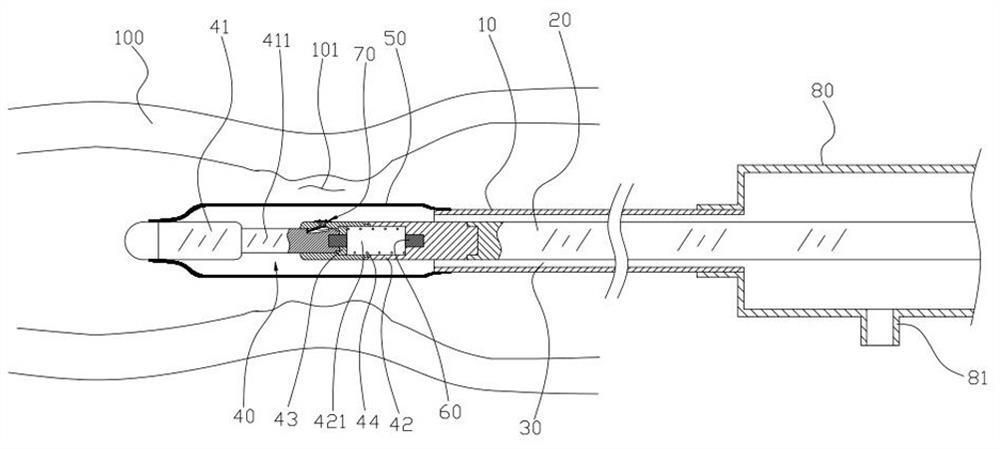
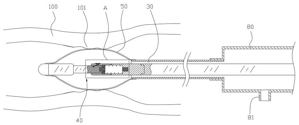
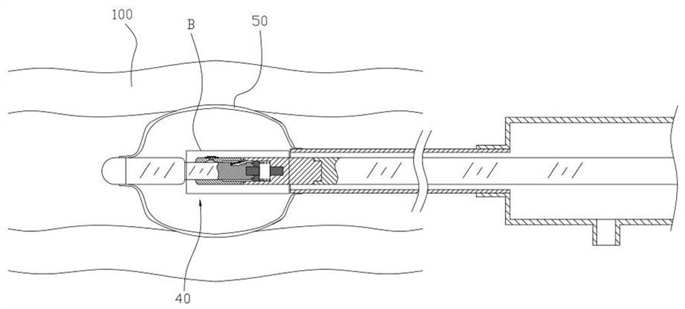
The invention discloses a catheter balloon, comprising: a core wire; an outer tube, which is sheathed on the outside of the core wire, and defines a flow path for fluid to pass through with the core wire; an adjustment mechanism, which includes a fixed part and a movable part, The fixed part is attached to the distal end of the core wire, the fixed part is provided with a guide hole in the axial direction, and the movable part has a guide column for cooperating with the guide hole; the force applying part is used to apply force to the movable part so that the guide column Able to slide toward the bottom of the guide hole; a trigger mechanism having a locked state for keeping the guide post at a position away from the bottom of the guide hole and an unlocked state for allowing the guide post to slide freely; a balloon, Its two ends are respectively sealed and attached to the distal end of the outer tube and the movable part, and the inside of the balloon communicates with the flow channel; wherein: the trigger mechanism is located inside the balloon, and the trigger mechanism is based on the pressure of the fluid supplied to the inside of the balloon And switch from the locked state to the unlocked state.

Description

technical field [0001] The invention relates to the technical field of medical instruments, in particular to a catheter balloon for interventional operations. Background technique [0002] During interventional surgery, when the stenosis of the blood vessels in the human body is found, the stenosis area is usually mechanically expanded by the catheter balloon (the stenosis area is mechanically expanded to minimize the degree of stenosis) ), specifically, the catheter balloon usually includes an outer tube, a core wire passing through the outer tube, and a balloon. The distal end of the core wire protrudes from the distal end of the outer tube. end and the distal end of the outer tube, the shape of the balloon is generally sleeve-like when it is not under fluid pressure. A channel for liquid to pass is defined between the outer tube and the core wire, and the proximal end of the outer tube communicates with the fluid supply device. [0003] When the outer tube is used to de...

Claims


Application Information

Patent Timeline
Patent Type & Authority Patents(China)
IPC IPC(8): A61M25/10
CPCA61M25/1002A61M25/1018
Inventor 许永松吴健秦川穆磊唐航
Owner BEIJING TAIJIE WEIYE TECH
Learn More