
A seamless expansion and contraction device for the detection surface of a medium-low speed maglev track sensor

A technology of seamless telescopic and magnetic levitation track, which is applied in the direction of tracks, roads, buildings, etc., can solve the problems of poor economy of the bridge substructure, inability to adapt to the rail joint value, and thick piers, so as to save manufacturing and construction difficulty and save structural engineering Investment, the effect of reducing the cross-sectional size of bridge piers

Active Publication Date: 2020-07-28
CHINA RAILWAY MAGLEV TRANSPORTATION INVESTMENT CONSTR CO LTD +1
View PDF8 Cites 0 Cited by
  • Summary
  • Abstract
  • Description
  • Claims
  • Application Information

AI Technical Summary

Problems solved by technology

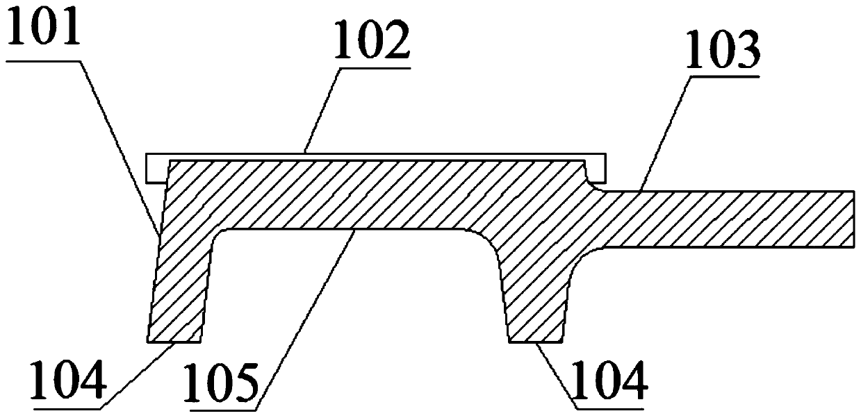
[0003] as attached figure 1 As shown, the patent CN201810649690 discloses a continuous magnetically conductive magnetic levitation track joint. A connecting bracket with a groove-shaped cavity and a magnetically conductive elastic body that is filled in the groove-shaped cavity and strongly bonded to the connecting bracket are provided at the rail seam position , so that there is no longer a broken seam in the F rail in the longitudinal direction, which can ensure the continuous magnetic conduction of the F rail in the longitudinal direction, and can automatically adapt to the longitudinal deformation of the rail row, but the magnetic elastic body of the expansion joint is up and down when the rail expands There will be bulging or concave deformation, and the unevenness of the detection surface of the suspension sensor at the local position of the rail gap will cause a sudden change in the elevation of the rail surface detected by the suspension sensor, which will affect the comfort of the maglev train and the suspension stability of the suspension frame
Since the magnetically conductive elastic body filled in the rail gap cannot be infinitely compressed, in order to limit the bulging or concave deformation of the detection surface of the suspension sensor to within the allowable range when the magnetically conductive elastic body expands and expands on the rail, the stretching device can only adapt to the maximum The rail gap value of no more than 40mm is equivalent to the expansion and contraction of the existing I-type expansion joints, and cannot adapt to a larger rail gap value
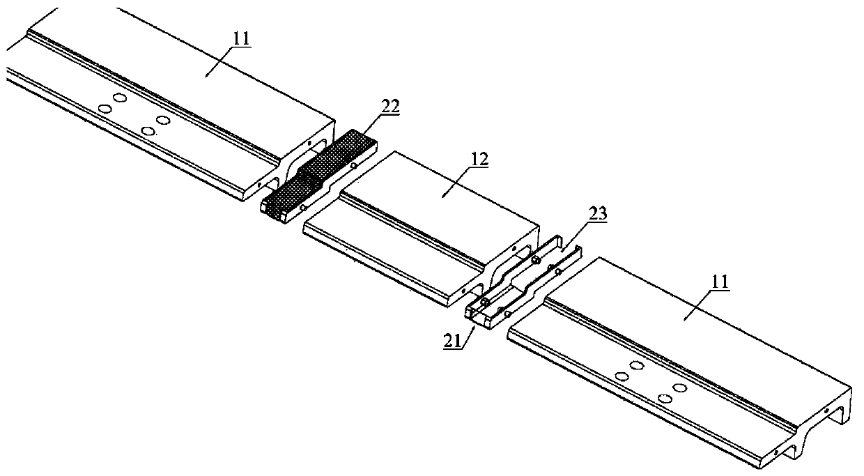
[0004] as attached figure 2 As shown, the patent CN201710266709 discloses a magnetic levitation rail row joint and a magnetic levitation track. Through the concave-convex cooperation of the main joint and the auxiliary joint, a magnetic pole surface without excessive gaps is formed, and the existence of the spaced end face is avoided. However, the main joint and the auxiliary joint of this patent The concave-convex fit structure of the joint will cause step-like irregularities on the detection surface of the suspension sensor when the track expands and contracts, which will affect the stability of the suspension control when the maglev vehicle passes through the rail gap. The suspension frame cannot pass through the rail gap
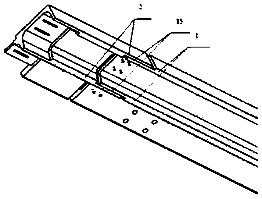
[0005] as attached image 3 And attached Figure 4 As shown in the patent documents CN201610517393 and CN201610517600 patents, the medium and low-speed maglev track with a rail-row connection device that ensures continuous signal acquisition is realized by setting a floating detection surface lower connection plate (one end is fixed and the other end is provided with a long round hole) at the position of the F-rail rail seam. The track adapts to the stretching and deformation of the rail row in the longitudinal direction and effectively ensures the continuous and uninterrupted maglev signal. However, the detection surface of the suspension sensor at the track seam position of this patent is affected by the lower connecting plate. The uneven shape will affect the stability of the suspension control when the vehicle passes through the rail gap, and the larger the rail gap width, the greater the thickness of the lower connecting plate required, and the step-like irregularity of the detection surface of the suspension sensor is about serious. When the irregularity exceeds a certain When the limit value (about 1mm), the unevenness caused by the construction error of the superimposed track structure, it is easy to cause the suspension frame to fail to pass through the rail gap
[0006] To sum up, the existing patents realize the continuous signal acquisition of the suspension sensor when it passes through the rail gap by setting the magnetically conductive elastic body, the concave-convex matching structure of the main joint and the auxiliary joint, and the connecting plate under the suspension detection surface, but there are rail gaps in all of them. Problems such as local unevenness or step-like unevenness affect the suspension control stability and the passing performance of the suspension frame, and these expansion devices or expansion joints can only adapt to a small rail gap value (generally not greater than 40mm), which is different from the existing I The expansion and contraction of the type expansion joints is equivalent, and it cannot adapt to a larger rail joint value. The extremely small expansion of the rail joint will eventually lead to an extremely small longitudinal displacement limit of the bridge pier top (generally not greater than 10mm), so the bridge pier needs to be designed to be thicker , the economy of the bridge substructure is very poor

Method used


Image

  • A seamless expansion and contraction device for the detection surface of a medium-low speed maglev track sensor
  • A seamless expansion and contraction device for the detection surface of a medium-low speed maglev track sensor
  • A seamless expansion and contraction device for the detection surface of a medium-low speed maglev track sensor

Examples


Embodiment Construction

[0043] In order to make the object, technical solution and advantages of the present invention clearer, the present invention will be further described in detail below in conjunction with the accompanying drawings and embodiments. It should be understood that the specific embodiments described here are only used to explain the present invention, not to limit the present invention. In addition, the technical features involved in the various embodiments of the present invention described below can be combined with each other as long as they do not constitute a conflict with each other.

[0044] Such as Figure 6 , Figure 7 and Figure 8 As shown, the present invention discloses a detection surface of a medium-low speed maglev track sensor. The seamless telescopic device for the detection surface of the sensor includes an F-shaped steel rail 1 , a telescopic mechanism for the sensing surface and a seamless telescopic mechanism 5 . Between two adjacent F-shaped steel rails 1, ...


PUM


Abstract

The invention discloses a seamless telescopic device for a detection surface of a medium-low speed magnetic levitation track sensor. The seamless telescopic device comprises an F-shaped steel rail (1), an induction surface telescopic mechanism and a seamless telescopic mechanism (5), wherein the F-shaped steel rail (1) is a steel rail with an F-shaped section; the induction surface telescoping mechanism comprises a fixed aluminum induction plate (3) and a joint-crossing aluminum induction plate (2). The limiting shells (503) are arranged at the head end and the tail end of the F-shaped steel rail (1), an end cover plate (504) is arranged at one end in each limiting shell (503), a fastening cover plate (505) is arranged at the other end in each limiting shell (503), the high-toughness curlysprings (502) surround cylindrical steel bars, and one ends of the high-toughness curly springs (502) are connected with flexible curls. According to the invention, a continuous telescopic suspensionsensor detection surface is formed in the rail gap distance range of the F-shaped steel rail, and no rail gap is locally uneven or step-shaped unsmooth, so that the comfort of a maglev train passingthrough the rail gap is better.

Description

technical field [0001] The invention belongs to the technical field of maglev track equipment, and more specifically relates to a seamless expansion and contraction device for the detection surface of a medium-low speed maglev track sensor. Background technique [0002] The medium and low-speed maglev rail transit adopts the suspension and guidance technology of the constant electromagnet suction type, and realizes the suspension and guidance of the vehicle through the electromagnetic attraction between the U-shaped electromagnet on the vehicle suspension frame and the F-shaped rail. The existing technology of medium and low-speed maglev transportation uses a slotted track to adapt to the expansion and contraction deformation of the bridge structure. [0003] as attached figure 1 As shown, the patent CN201810649690 discloses a continuous magnetically conductive magnetic levitation track joint. A connecting bracket with a groove-shaped cavity and a magnetically conductive el...

Claims


Application Information

Patent Timeline
Patent Type & Authority Patents(China)
IPC IPC(8): E01B25/30
CPCE01B25/30
Inventor 龚俊虎谢海林鄢巨平张家炳韦随庆刘武斌章致张宝华李伟强丁兆锋金陵生孙斌
Owner CHINA RAILWAY MAGLEV TRANSPORTATION INVESTMENT CONSTR CO LTD
Learn More