Energy-saving and environment-friendly farmland fertilization device
An energy-saving, environmental-friendly, and fertilizing device technology, which is applied in fertilizing devices, energy-saving measures, agriculture, etc., can solve the problems of inability to fertilize, labor-intensive, and low fertilizing efficiency, and achieves improved fertilization effect, increased cleanliness, and improved fertilization. effect of potency
- Summary
- Abstract
- Description
- Claims
- Application Information
AI Technical Summary
Problems solved by technology
Method used
Image
Examples
Embodiment 1
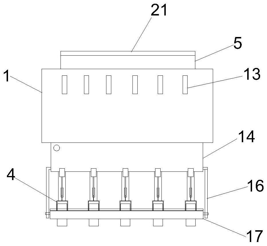
[0062] Such as Figure 1-2 As shown, an energy-saving and environment-friendly farmland fertilization device; including a box body 1; a storage box 14 is connected to the bottom of the box body 1, and a plurality of second connecting rods 20 are connected to one side of the box body 1, and a plurality of The second connecting rod 20 is connected with a fertilization mechanism 2; the bottom of the storage box 14 is connected with a plurality of connecting columns 18, and the bottom of the plurality of connecting columns 18 is connected with a soil covering mechanism 3; one of the storage boxes 14 The side is connected with a plurality of first connecting rods 15, and a plurality of the first connecting rods 15 are provided with a suppression mechanism 4; the fertilization mechanism 2, the soil covering mechanism 3, and the suppression mechanism 4 are arranged in sequence; Be provided with feed inlet 5, the top of described feed inlet 5 is provided with dodge door 21, and dodge ...
Embodiment 2
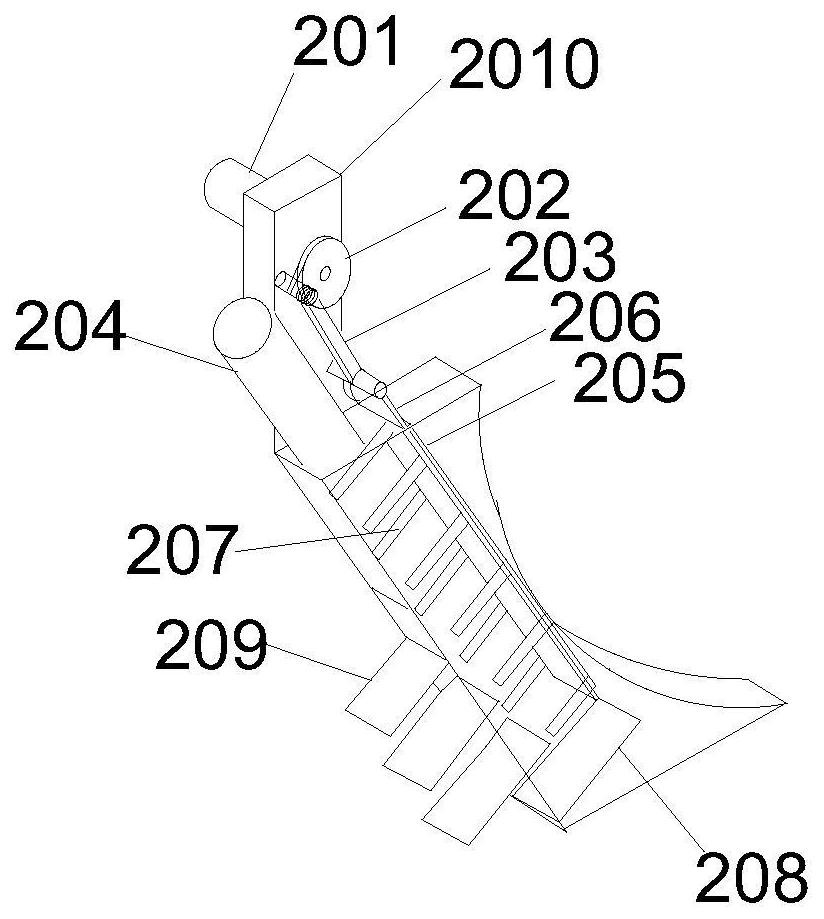
[0075] On the basis of Example 1, as image 3 , 6 As shown in -9, the fertilization mechanism 2 includes an outer casing, and the inside of the outer casing is a hollow structure; the top of the outer casing is provided with a second motor 201, and the second motor 201 is connected to a reducer 2010, and the output end of the reducer 2010 A cam disc 202 is connected; a connecting rod 203 is eccentrically connected on the cam disc 202; the other end of the connecting rod 203 is connected with a sliding plate 206; one side of the outer casing is provided with a slideway 205, and the sliding plate 206 is arranged inside the slideway 205 , and the slide plate 206 forms a sliding connection with the outer casing through the slideway 205 .
[0076] One side of the second motor 201 is provided with a feeding pipe 204, and the feeding pipe 204 is arranged on the top of the outer casing, and the lower feeding pipe 204 communicates with the bottom of the casing 1; one side of the outer...
Embodiment 3
[0081] Such as Figure 4-5 As shown, on the basis of Embodiment 1, the suppression mechanism 4 includes a connecting piece 41, the top end of the connecting piece 41 is connected with the first connecting rod 15, and the lower end of the connecting piece 41 is connected with a movable piece 42. The part 42 is a "U" shaped part, and the movable part 42 is movably connected with a fixed part 43 through a pin shaft, and a running wheel 44 is rotatably connected with the lower part of the fixed part 43 .
[0082] The fixed member 43 is connected with a fixed rod 17, and the fixed rod 17 connects a plurality of suppression mechanisms 4 together; the fixed rod 17 is connected with a support rod 16, and the other end of the support rod 16 is connected with the first Rod 15 is flexibly connected.
PUM
| Property | Measurement | Unit |
|---|---|---|
| Angle | aaaaa | aaaaa |
| Diameter | aaaaa | aaaaa |
| Pitch | aaaaa | aaaaa |
Abstract
Description
Claims
Application Information
 - Generate Ideas
- Intellectual Property
- Life Sciences
- Materials
- Tech Scout
- Unparalleled Data Quality
- Higher Quality Content
- 60% Fewer Hallucinations
Browse by: Latest US Patents, China's latest patents, Technical Efficacy Thesaurus, Application Domain, Technology Topic, Popular Technical Reports.
© 2025 PatSnap. All rights reserved.Legal|Privacy policy|Modern Slavery Act Transparency Statement|Sitemap|About US| Contact US: help@patsnap.com


