
Redundant flexible contact point contact inertia switch

An inertial switch and flexible technology, applied in the field of inertial switches, can solve the problems of short closing time, easy breakage or deformation, and low reliability of the switch, and achieve the effect of universal structural design, improving the reliability of action, and prolonging the closing time

Active Publication Date: 2021-02-26
中国兵器装备集团自动化研究所有限公司
View PDF11 Cites 3 Cited by
  • Summary
  • Abstract
  • Description
  • Claims
  • Application Information

AI Technical Summary

Problems solved by technology

[0005] Most of the switches are single-way switches. Once they fail, the entire system will not work, causing projectiles or fuzes to misfire, and the reliability is low.
[0006] The switch does not have the ability to resist high overload: the working environment of the projectile and the fuze is harsh, especially in the accidental drop in the firing chamber and the service, the impact load of the switch can reach tens of thousands of g, and the switch is prone to breakage or failure under such high overload conditions. out of shape
[0007] The closing time of the switch is short: the current closing contact of the switch has too many rigid contacts. When the projectile is launched or hits the target, the switch is closed; Misidentification or higher requirements for electronic control components

Method used


Image

  • Redundant flexible contact point contact inertia switch
  • Redundant flexible contact point contact inertia switch
  • Redundant flexible contact point contact inertia switch

Examples


Embodiment

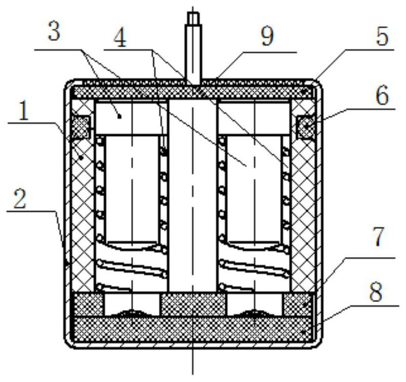
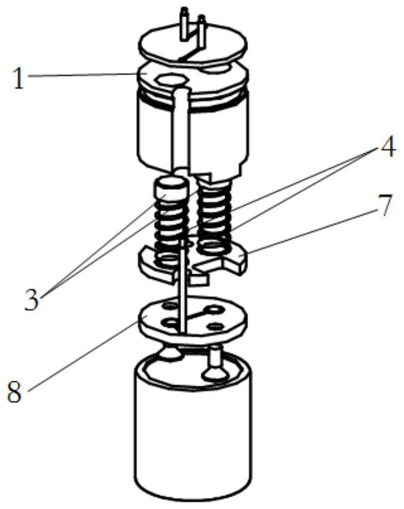
[0036] Such as Figure 1-2 As shown, an inertial switch with redundant flexible contact contact includes an insulating body, a metal shell, two inertia pins, two inertia springs, a lead PCB board, a conductive PCB board and an insulating PCB board, wherein the insulating body, two One inertia pin, two inertia springs, lead PCB board, conductive PCB board and insulating PCB board are all set inside the metal case; lead wire PCB board is located at the top of the metal case; conductive PCB board and insulating PCB board are located at the bottom of the metal case, and The insulating PCB board is located above the conductive PCB board, and the insulating PCB board supports the two inertia springs; the insulating body is distributed on the side of the metal shell to form an inner hole of the insulating body, and the insulating body is located between the lead PCB board and the insulating PCB board; the two Two inertia springs are respectively placed on the two inertia pins to form...


PUM


Abstract

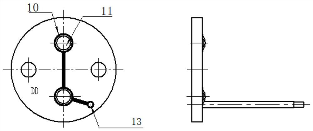
The invention discloses a redundant flexible contact point contact inertia switch. The switch comprises a metal shell; an insulating body, two inertia pins, two inertia springs, a lead PCB, a conductive PCB and an insulating PCB are arranged in the metal shell; the lead PCB is positioned at the top end of the metal shell; the conductive PCB and the insulating PCB are both located at the bottom endof the metal shell, and the insulating PCB is located above the conductive PCB; the insulating body is distributed on the side surface of the metal shell to form an insulating body inner hole and ispositioned between the lead PCB and the insulating PCB; and the two inertia springs are respectively sleeved on the two inertia pins to form two whole bodies, and then the two whole bodies are arranged in the insulating body inner hole. Double sets of inertia pin redundancy design are adopted, so that the action reliability of the inertia switch under a launching or collision condition is greatlyimproved; the conductive PCB is provided with copper-clad surfaces and flexible electrodes corresponding to the vertical positions of the inertia pins; with the flexible electrodes designed, the switching-on time of the switch can be prolonged, and therefore, the subsequent recognition of a switching-on signal by an electronic control part can be facilitated.

Description

technical field [0001] The invention relates to the technical field of inertial switches, in particular to an inertial switch with redundant flexible contact contacts. Background technique [0002] The inertial switch is closed by using the recoil force or forward momentum generated when the carrier launches or hits the target, and realizes the function of switching the circuit from opening to closing. The inertial switch has a wide demand in projectiles or electromechanical fuzes, and is an important component for projectiles or fuzes to realize the functions of launching release, triggering detonation, or landing self-destruction. [0003] The current inertia switch mainly has two kinds of radial contact mode and universal contact mode. The universal contact switch has high reliability, but its structure is complicated, it requires high processing and assembly technology, and it is difficult to withstand high overload conditions; the radial contact switch is designed with...

Claims


Application Information

Patent Timeline
IPC IPC(8): H01H35/14
CPCH01H35/146H01H35/141
Inventor 马婷霞欧阳长青刘玲罗凌江胡阳
Owner 中国兵器装备集团自动化研究所有限公司
Learn More