
Fluorescence imaging device applying spectrum detection and testing method

A technology of fluorescence imaging and spectral detection, which is applied in measurement devices, fluorescence/phosphorescence, and material analysis through optical means, and can solve the problems that the position and boundary are difficult to accurately determine and difficult to find.

Active Publication Date: 2021-02-26
SOUTH CHINA NORMAL UNIVERSITY
View PDF6 Cites 1 Cited by
  • Summary
  • Abstract
  • Description
  • Claims
  • Application Information

AI Technical Summary

Problems solved by technology

However, because some specific target protein sites are not easy to be found or in deep tissues, its position and boundary are difficult to accurately determine

Method used


Image

  • Fluorescence imaging device applying spectrum detection and testing method
  • Fluorescence imaging device applying spectrum detection and testing method
  • Fluorescence imaging device applying spectrum detection and testing method

Examples


Embodiment Construction

[0028] Next, the technical solutions in the embodiments of the present invention will be clearly and completely described in conjunction with the accompanying drawings of the present invention, and the described embodiments are only some of the embodiments of the present invention, not all of them. Based on the embodiments of the present invention, other embodiments obtained by persons of ordinary skill in the art without making creative efforts all belong to the protection scope of the present invention.

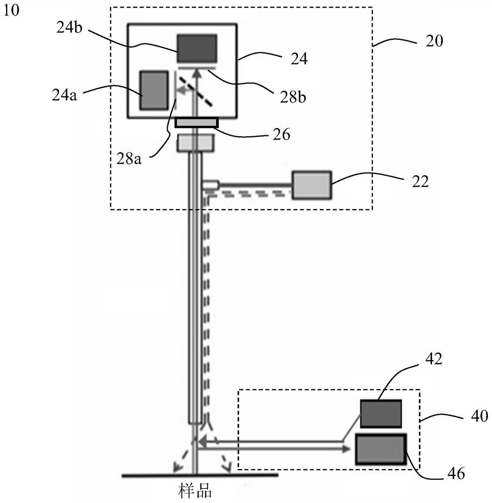
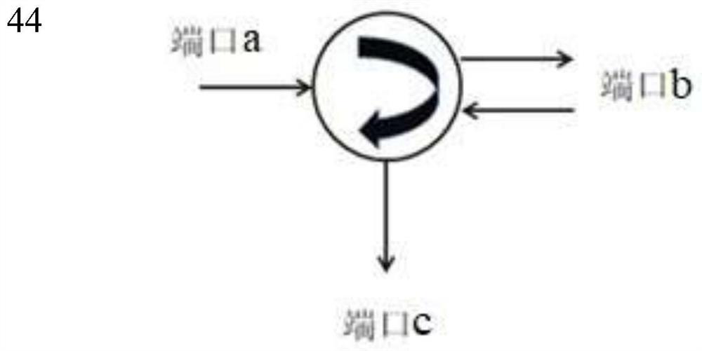
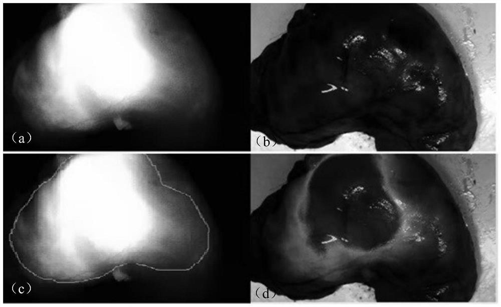
[0029] The present invention will be described in further detail below. In one embodiment, refer to figure 1 , the fluorescence imaging device 10 using spectral detection includes an imaging unit 20 and a spectral detection unit 40, the imaging unit 20 includes an imaging light source 22 and a dual image sensor 24, and the imaging light source 22 includes a visible light source and a first near-infrared excitation light source. The visible light source is, for example, a w...


PUM

PropertyMeasurementUnit
wavelengthaaaaaaaaaa

Abstract

The present invention relates to a fluorescence imaging device and a test method using spectral detection, the imaging device comprising: an imaging unit and a spectrum detection part. The imaging unit is used for emitting visible light and near-infrared light to a specimen having a specific targeting fluorescent protein therein and converting the visible light and near-infrared light into a visible light image and a near-infrared light image; an area with the highest fluorescence brightness is selected as a reference area, an area with the fluorescence brightness weaker than that of the reference area by a certain degree is selected as an area to be detected, near-infrared excitation light of a spectrum detection part is adopted to irradiate the area to be detected, and a spectrograph isadopted to detect the peak wavelength of fluorescence emitted by the area to be detected. And the peak wavelength of the area is compared with the highest fluorescence brightness with the peak wavelength of the are to be detected, and the boundary region of the specific targeting fluorescent protein is determined. According to the fluorescence imaging device, the spectrograph is introduced, and the position and the boundary region of the specific targeting fluorescent protein are distinguished by accurately measuring the peak wavelength through the spectrograph by utilizing the characteristicsof the specific targeting fluorescent protein.

Description

technical field [0001] The invention relates to the field of imaging, in particular to a fluorescence imaging device and a testing method using spectrum detection. Background technique [0002] The optical molecular imaging method is applied to endoscopic imaging. By injecting specific protein-targeting fluorescent reagents and using two light sources, white light and excitation light, to illuminate the sample area, clear color images of the imaging area and reaction-specific targeting are simultaneously obtained. Fluorescent images of proteins. This method can perform in vivo imaging of specifically targeted protein fluorescent tissue at the molecular level of tumor cells, and has the advantages of low cost, high throughput, non-invasive, non-contact, non-ionizing radiation, high sensitivity, and high specificity. However, because some specific target protein sites are not easy to be found or are located in deep tissues, their positions and boundaries are difficult to accu...

Claims


Application Information

Patent Timeline
Patent Type & Authority Applications(China)
IPC IPC(8): G01N21/64
CPCG01N21/6486
Inventor 朱凝王娟丽魏波邵军郑晓明
Owner SOUTH CHINA NORMAL UNIVERSITY
Learn More