
A comprehensive measuring mechanism

A technology of comprehensive measurement and driving mechanism, which is applied in the direction of measuring device, mechanical diameter measurement, mechanical measuring device, etc., can solve the problems that the piston size cannot be guaranteed, the number of piston turnover times is too high, and the product qualification rate is affected, so as to achieve a stable and reliable detection process , save manpower, reduce the effect of the chance of bumping and scratching

Active Publication Date: 2022-07-05
BINZHOU BOHAI PRECISION MACHINERY +1
View PDF11 Cites 0 Cited by
  • Summary
  • Abstract
  • Description
  • Claims
  • Application Information

AI Technical Summary

Problems solved by technology

[0004] However, in the prior art, the relevant dimensions of the piston pin hole are mostly measured by multiple manual processes or by random inspection using general-purpose measuring tools, which not only wastes manpower, but also causes many turnovers of the piston during the measurement process, which is prone to bumps, scratches, etc. Phenomenon that affects the qualification rate of the product
Compression and other dimensions need to be measured with general-purpose measuring tools. Due to the low efficiency, only random inspection can be used, which makes it impossible to ensure that all pistons are qualified in size
Although there are some simple piston pin hole detection equipment, generally only a few dimensions can be measured, and when the pin hole diameter and pin hole roundness are measured, the pin hole air probe is generally used, and the two pin hole probes are inserted respectively. In the piston pin hole on the side, the measurement is divided into several times, which is more cumbersome and the detection accuracy is poor

Method used


Image

  • A comprehensive measuring mechanism
  • A comprehensive measuring mechanism
  • A comprehensive measuring mechanism

Examples


Embodiment Construction

[0042] In order to understand the above objects, features and advantages of the present invention more clearly, the present invention will be further described in detail below with reference to the accompanying drawings and specific embodiments. It should be noted that the embodiments of the present application and the features in the embodiments may be combined with each other in the case of no conflict.

[0043] Many specific details are set forth in the following description to facilitate a full understanding of the present invention. However, the present invention can also be implemented in other ways different from those described herein. Therefore, the protection scope of the present invention is not limited by the specific details disclosed below. Example limitations.

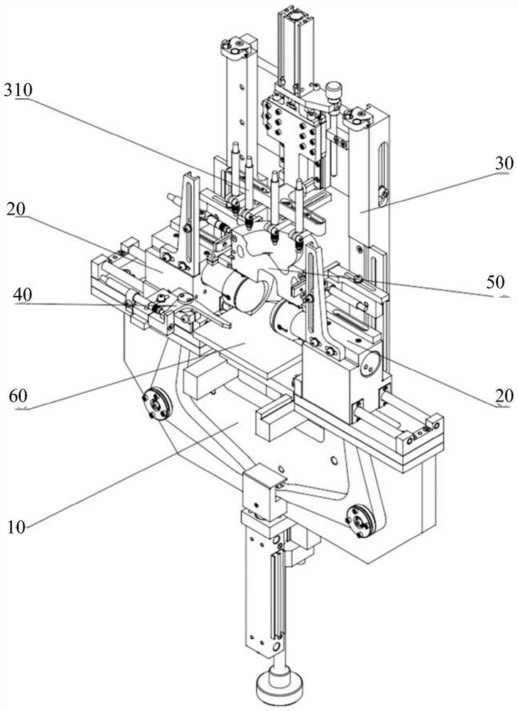
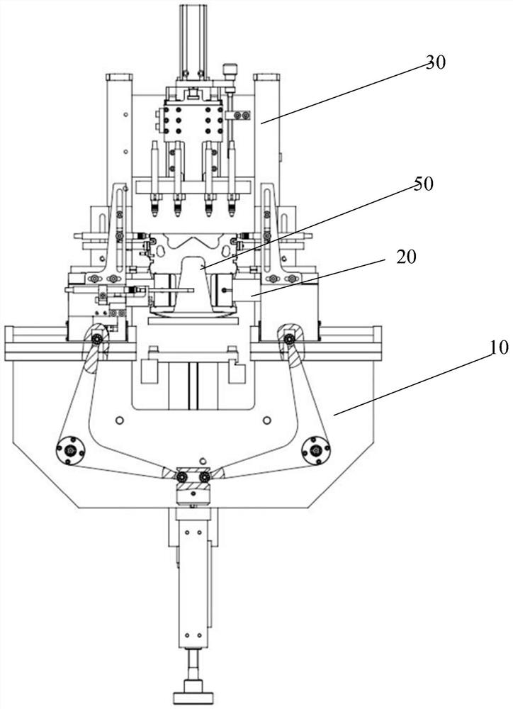
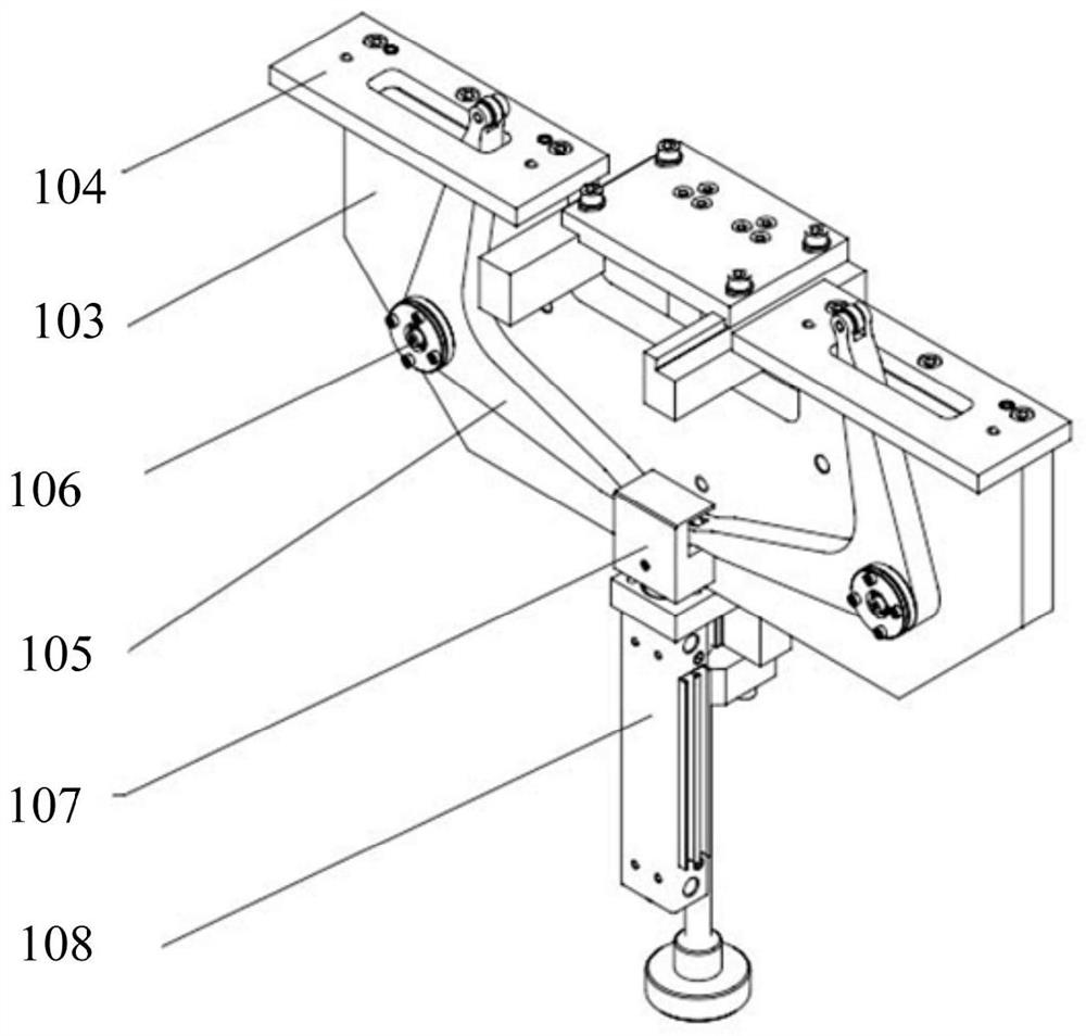
[0044] Combine below Figure 1 to Figure 7 The comprehensive measurement mechanism according to the embodiment of the present invention will be specifically described.

[0045] like figure 1 and fig...


PUM


Abstract

The invention provides a comprehensive measuring mechanism, comprising: a position adjustment component including an installation guide rail, which is fixedly installed on a work table, a piston placing plate is arranged on a fixed plate between the installation guide rails, and the bottom surface of the fixed plate is fixedly connected to the adjustment plate, The installation plate is connected with the adjustment plate, and the plug gauge drive mechanism installation plate is fixedly connected to the installation plate. The right-angle end is connected with the plug gauge drive mechanism, and the pull block is connected with the first cylinder; the two plug gauge drive mechanisms are respectively installed on the plug gauge drive mechanism mounting plates on the left and right sides of the mounting plate, and the plug gauge mounting seat is connected to the right angle. The arm is connected. Through the technical scheme of the present invention, the number of turnovers in the piston detection process is reduced, the probability of bumping and scratching is effectively reduced, and the use is convenient, the detection efficiency is high, the detection process is stable and reliable, manpower is saved, and multiple key dimensions of the piston can be realized. Comprehensive testing.

Description

technical field [0001] The invention relates to the technical field of dimension detection of automobile parts, in particular to a comprehensive measuring mechanism. Background technique [0002] The size of the piston pin hole is the key size of the piston. The piston pin hole and the piston pin should maintain a reasonable fit gap to ensure that there is enough lubricating oil film between the piston pin and the pin hole, and there will be dryness between the thin-faced piston pin hole and the piston pin. Generally speaking, when the fitting clearance between the piston pin and the piston pin hole is 6-8 μm, the normal operation of the piston can be guaranteed. [0003] The dimensions related to the piston pin hole also include the symmetry between the pin hole axis and the outer circular axis (ie the offset of the piston pin hole), the perpendicularity between the pin hole axis and the outer circular axis, and the distance from the pin hole axis to the top surface of the ...

Claims


Application Information

Patent Timeline
Patent Type & Authority Patents(China)
IPC IPC(8): G01B21/22G01B21/24G01B21/02G01B21/08G01B21/10G01B21/20G01B21/18G01B5/08G01B5/20G01B5/00
CPCG01B21/22G01B21/24G01B21/02G01B21/08G01B21/10G01B21/20G01B21/18G01B5/08G01B5/201G01B5/003G01B5/0002Y02E30/30
Inventor 刘昭王溪田志远李佃州王秀松陈瀚庞兆杰车忠堂
Owner BINZHOU BOHAI PRECISION MACHINERY
Learn More