Hydraulic control one-way valve

A hydraulically controlled one-way valve and valve stem technology, applied in the direction of control valves, lift valves, valve devices, etc., can solve the problems of leakage at the joint, difficult to clean, difficult to disassemble, etc., to achieve high joint stability, convenient cleaning, and connection solid effect

Pending Publication Date: 2021-02-26
金继余
View PDF5 Cites 0 Cited by
  • Summary
  • Abstract
  • Description
  • Claims
  • Application Information

AI Technical Summary

Problems solved by technology

[0003] Although the above-mentioned structure is ingeniously designed, the connection between the valve stem and the control piston adopts a threaded connection. When it is necessary to ensure sufficient sealing, the connection force will be very large and it is not easy to disassemble. Impurities accumulate in the connection hole, and when a blockage is formed, it is difficult to clean up, and once the threaded connection force is insufficient, leakage at the butt joint is prone to occur

Method used


Image

  • Hydraulic control one-way valve
  • Hydraulic control one-way valve
  • Hydraulic control one-way valve

Examples


Embodiment

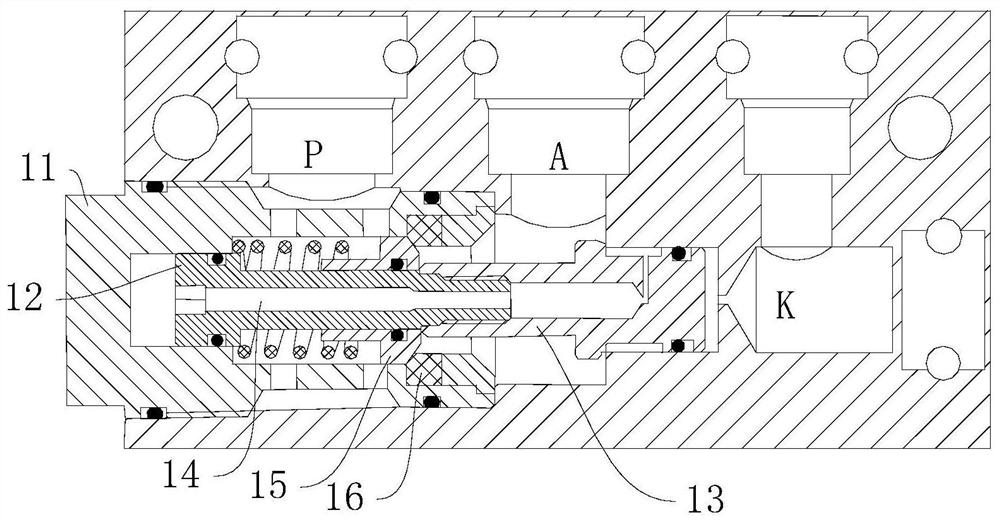
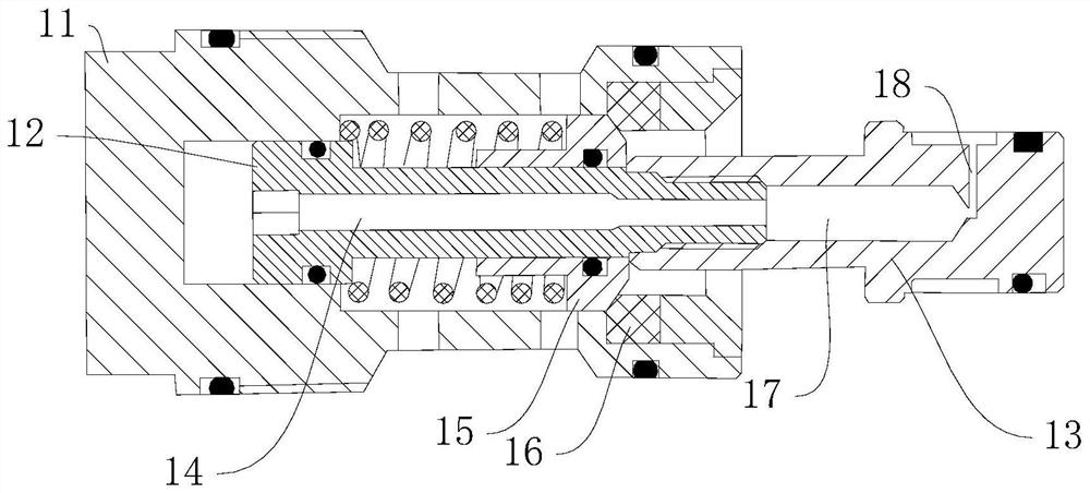
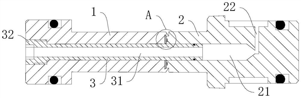
[0030] A hydraulically controlled one-way valve, see attached Figure 3-10 , since this solution only involves the improvement of the valve stem 1 and the control piston 2, the structure of the rest of the parts will not be introduced too much.

[0031] The valve stem 1 includes a communication hole 12 through which the inside passes, and a lock chamber 11 concentric with the communication hole 12 is provided at one end of the valve stem 1 , and a socket end is provided at the other end, and the socket end is used for engaging with the control piston 2 . Wherein the control piston 2 includes a docking hole 21 matched with the connecting hole, and the docking hole 21 does not pass through the control piston 2 , and the diameter of the docking hole 21 is consistent with that of the communication hole 12 . The peripheral surface of the control piston 2 is also provided with a throttling hole 22 communicating with the docking hole 21, and the throttling hole 22, the docking hole 2...


PUM


Abstract

The invention discloses a hydraulic control one-way valve. The hydraulic control one-way valve comprises a valve rod and a control piston, wherein a through communication hole is arranged in the valverod in a penetrating mode; a butt joint hole matched with the communication hole is arranged in the end, facing the valve rod, of the control piston; the butt joint hole does not penetrate through the control piston; an orifice communicated with the butt joint hole is arranged in the peripheral wall of the control piston; the communication hole, the butt joint hole and the orifice are communicated with one another; a clamping mechanism is arranged between the opposite sides of the valve rod and the control piston; the clamping mechanism comprises a clamping block arranged at the end of the control piston and a clamping groove arranged in the end, facing the control piston, of the valve rod; a hollow control rod is arranged in the communication hole in a penetrating and matched mode; the control rod controls the clamping block to be clamped into or separated from the clamping groove, after the clamping end of the control piston is inserted into an inserting cavity of the valve rod, primary positioning sealing is achieved, after the control rod is inserted, the clamping end of the clamping block can be inserted into the clamping groove of the inserting cavity, rigid and firm fixingbetween the control piston and the valve rod is achieved, the installation is convenient, and the connection is stable.

Description

technical field [0001] The invention relates to the technical field of valves, in particular to a hydraulic control check valve. Background technique [0002] The hydraulic control check valve is the basic component in the electro-hydraulic control system. By controlling the hydraulic control check valve, the orderly movement of each cylinder of the hydraulic support can be realized. In the prior art, in order to solve the problem of unloading impact, in the Chinese patent with the application number CN201910810089.0 and the name of the hydraulic control check valve, a check valve structure is adopted, and its structure is shown in the attached figure 1 with 2 , mainly including a screw sleeve 11, a valve stem 12, a valve seat 16, a valve core 15, a spring and a control piston 13, wherein the valve stem 12 is covered with a valve core 16, which is formed with the valve seat 16 arranged in the screw sleeve 11 Cooperate, the spring presses against the valve core 15 and the v...

Claims


Application Information

Patent Timeline
Patent Type & Authority Applications(China)
IPC IPC(8): F16K1/32F16K15/06F15B13/02
CPCF15B13/027F16K1/32F16K15/063
Inventor 左成林许泉彬
Owner 金继余
Why Eureka
Try Eureka