


Quick Research
Generate reliable direction feasibility study reports for your R&D in just a few steps.

Technical Q&A
Discover and master advanced knowledge NOW. Basics, ideas, possibilities, all at once.

Find Solutions
As an expert in R&D theories, this can generate solutions to your technical problems instantly.

Evaluate Feasibility
Analyze your overall solution with one click, know your potential R&D risks in advance.

Monitor Landscape
Get weekly tech updates, stay abreast of the latest tech innovations and key insights.
A smart energy-saving screw blower gas station
A blower and screw technology, which is applied in the field of intelligent energy-saving screw blower gas stations, can solve the problems of inconvenient discharge of blower air, rising temperature, and lower heat dissipation quality of blower components, so as to improve the quality of the working environment, improve the utilization rate, and have a simple structure Effect
- Summary
- Abstract
- Description
- Claims
- Application Information
AI Technical Summary
Problems solved by technology
Method used
Image

Examples
Embodiment 1
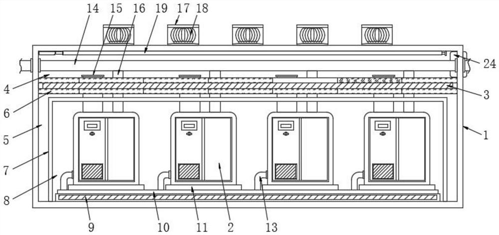
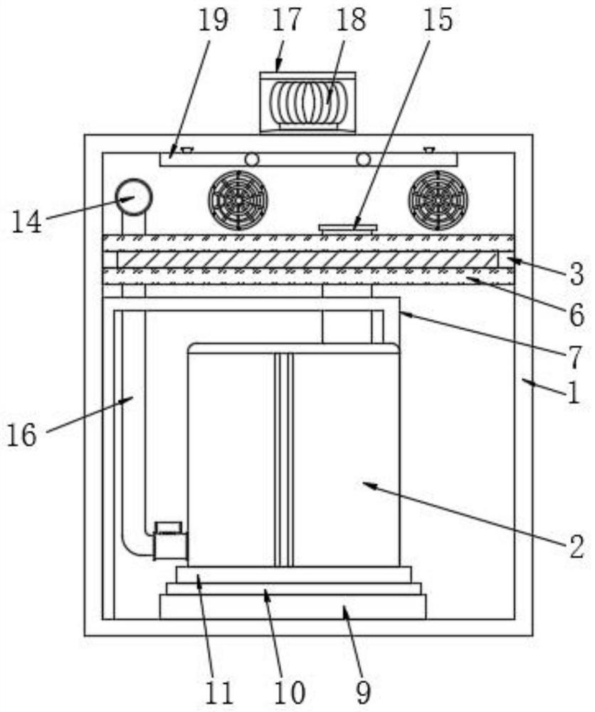
[0037] see Figure 1-2 As shown, a smart energy-saving screw blower gas station includes a gas station body 1, several screw blowers 2 and a smart IoT system. The air intake of the screw blower 2 adopts the fresh air outside the gas station. The inside of the gas station body 1 is fixedly connected with a fence plate 3, and the interior of the gas station body 1 is respectively provided with a pipeline room 4 and an equipment room 5 on the upper and lower sides of the fence plate 3, and the upper and lower surfaces of the fence plate 3 are glued together. The insulation board 6 is connected together, and the interior of the equipment room 5 is fixedly connected with the insulation partition 7. The insulation partition 7 is assembled with a detachable structure, and the detachable structure adopts buckles and bolts, so as to facilitate the insulation partition 7 for installation and disassembly, the area inside the insulation partition 7 forms the air inlet chamber 8, and the i...
Embodiment 2
[0048] see Figure 6 As shown, several exhaust windows 12 are provided on the side of the pipeline chamber 4, and the tops of the exhaust pipes 15 are fixedly connected to the exhaust windows 12 respectively.
[0049] The working principle of this embodiment: Arrange compressed air pipes 14 inside the pipeline chamber 4, and set up exhaust windows 12, and assemble each exhaust pipe 15 with the exhaust windows 12;
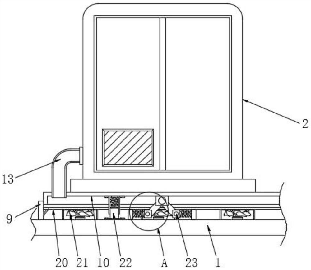
[0050] When the screw blower 2 is working, start the cooling fan 21. After the cooling fan 21 works, the external air is sucked into the ventilation plate 9, part of the air is sprayed to the bottom of the screw blower 2 through the buffer plate 10, and part of the air flows along the connecting pipe 13. Spray into the screw blower 2 to cool and dissipate the internal components of the screw blower 2, and then the air is discharged from the air station body 1 from the exhaust window 12 along the exhaust pipe 15;
[0051] The screw blower 2 vibrates during operation...
PUM
 Abstract
Description
Claims
Application Information
 - R&D Engineer
- R&D Manager
- IP Professional
- Industry Leading Data Capabilities
- Powerful AI technology
- Patent DNA Extraction
Browse by: Latest US Patents, China's latest patents, Technical Efficacy Thesaurus, Application Domain, Technology Topic, Popular Technical Reports.
© 2024 PatSnap. All rights reserved.Legal|Privacy policy|Modern Slavery Act Transparency Statement|Sitemap|About US| Contact US: help@patsnap.com