
Prefabricated elevator shaft

A technology of prefabricated shafts and elevator shafts, applied in the direction of vibration suppression adjustment, structural elements, building components, etc., can solve the problems of cast-in-place component formwork support, difficult operation of dismantling, labor-consuming and time-consuming elevator shaft space, unfavorable energy saving and environmental protection, etc., to achieve Save labor time cost, reduce on-site pouring, improve the effect of safety and earthquake resistance

Pending Publication Date: 2021-02-26
JIANGSU WANRONG ENG TECH CO LTD
View PDF0 Cites 0 Cited by
  • Summary
  • Abstract
  • Description
  • Claims
  • Application Information

AI Technical Summary

Problems solved by technology

At present, the existing elevator shafts include brick-laying shafts, steel structure elevator shafts and concrete elevator shafts. Among them, brick-laying shafts have more wet operations on site, many procedures, labor and time, and the space in the elevator shaft is small. The formwork of cast-in-place components Supporting and dismantling is not easy to operate, and it is not conducive to energy saving and environmental protection. The steel structure elevator shaft has the disadvantage of high raw material cost, while the concrete elevator shaft needs to be made by assembling steel bars and then filling concrete, which has the disadvantage of long construction period.

Method used


Image

  • Prefabricated elevator shaft
  • Prefabricated elevator shaft
  • Prefabricated elevator shaft

Examples


Embodiment Construction

[0030] The following will clearly and completely describe the technical solutions in the embodiments of the present invention with reference to the accompanying drawings in the embodiments of the present invention. Obviously, the described embodiments are only some, not all, embodiments of the present invention. Based on the embodiments of the present invention, all other embodiments obtained by persons of ordinary skill in the art without making creative efforts belong to the protection scope of the present invention.

[0031] In the description of the present invention, it should be noted that the orientation or positional relationship indicated by the terms "upper", "lower", "longitudinal", "horizontal", etc. is based on the orientation or positional relationship shown in the drawings, and is only for It is convenient to describe the present invention and simplify the description, but does not indicate or imply that the device or element referred to must have a specific orie...


PUM


Abstract

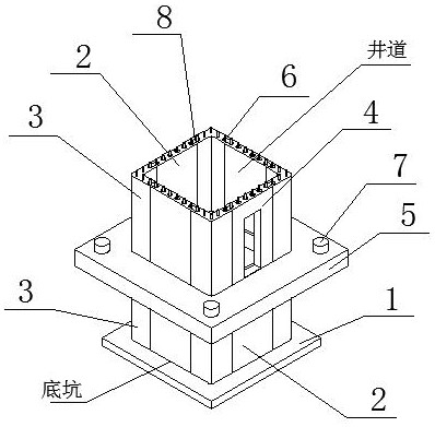
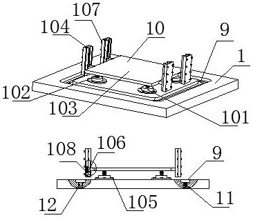
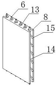
The invention discloses a prefabricated elevator shaft. The prefabricated elevator shaft comprises a base forming a bottom pit, a first prefabricated shaft plate and a second prefabricated shaft plate, and a shaft plate containing groove and an elevator falling protection device are arranged on the base. Except the first prefabricated shaft plate and the second prefabricated shaft plate, the prefabricated elevator shaft further comprises a third prefabricated shaft plate provided with an elevator opening and a prefabricated connecting plate used for connecting the bottom pit with a well or connecting the bottom pit with the well, the prefabricated connecting plate is a square ring body, and connecting grooves used for being connected with the prefabricated shaft plates and at least four first bolt holes used for fixing the prefabricated connecting plates are symmetrically formed in the prefabricated connecting plates. The prefabricated elevator shaft is formed by splicing the prefabricated shaft plates and the prefabricated connecting plates, installation is convenient, and on-site pouring is reduced; and meanwhile, a large amount of labor time cost is saved, the integrity and stability of the elevator shaft are enhanced, and potential safety hazards generated when an elevator falls are reduced.

Description

technical field [0001] The invention relates to the field of construction engineering, in particular to a prefabricated elevator shaft. Background technique [0002] With the continuous improvement of my country's economic level and construction level, more and more multi-storey, high-rise and super high-rise buildings have appeared, so elevators have become indispensable equipment. At present, the existing elevator shafts include brick-laying shafts, steel structure elevator shafts and concrete elevator shafts. Among them, brick-laying shafts have more wet operations on site, many procedures, labor and time, and the space in the elevator shaft is small. The formwork of cast-in-place components Supporting and dismantling is not easy to operate, and it is not conducive to energy saving and environmental protection. The steel structure elevator shaft has the disadvantage of high raw material cost, while the concrete elevator shaft needs to be made by assembling steel bars and ...

Claims


Application Information

Patent Timeline
IPC IPC(8): E04F17/00E04B1/343E04C5/16F16F15/067
CPCE04B1/34321E04B1/34331E04C5/163E04F17/005F16F15/067
Inventor 王艺潭王聪王优许丽娟陈迎
Owner JIANGSU WANRONG ENG TECH CO LTD
Learn More