Sewage treatment device and sewage treatment assembly

A sewage treatment device and sewage treatment technology, applied in the direction of oxidized water/sewage treatment, water/sewage multi-stage treatment, water/sludge/sewage treatment, etc. Sewage treatment costs and other issues, to achieve a high degree of automation, avoid clogging, and reduce labor force

Inactive Publication Date: 2021-02-26
西安中威环境技术有限公司
View PDF1 Cites 0 Cited by
  • Summary
  • Abstract
  • Description
  • Claims
  • Application Information

AI Technical Summary

Problems solved by technology

[0003] According to the Chinese patent network CN207418448U, although the chemical dosing sewage treatment device has solved the problem of fully integrating the chemical and sewage, it cannot automatically process the sludge, thereby increasing the labor force of the staff. The degree of automation is not high, and the cost of sewage treatment is increased.

Method used


Image

  • Sewage treatment device and sewage treatment assembly
  • Sewage treatment device and sewage treatment assembly

Examples


Embodiment 1

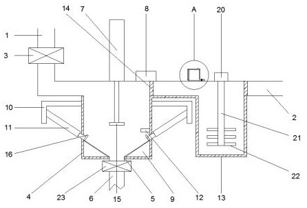
[0027] Example 1 as figure 1 As shown, a sewage treatment device and a sewage treatment assembly according to an embodiment of the present invention include a water inlet pipe 1 and an outlet pipe 2, the water inlet pipe 1 is equipped with a first electromagnetic valve 3, the water inlet pipe 1 is connected to the first box body 4, The outer wall of the lower end of the first box body 4 is provided with a sewage outlet 5, the sewage outlet 5 is connected with a sewage pipe 6, and the sewage pipe 6 is equipped with a second electromagnetic valve 23, and the outer wall of the upper end of the first box body 4 is embedded with a valve that matches the sewage outlet 5. The first electric push rod 7, the outer wall of the upper end of the first box body 4 is fixedly provided with a controller 8, the two ends of the inner wall below the first box body 4 are fixedly provided with symmetrical triangular blocks 9, and the outer walls of the first box body 4 both sides are fixedly provid...

Embodiment 2

[0029] Embodiment 2 is on the basis of embodiment 1 such as figure 1 As shown, for the grid, the connection between the first box body 4 and the water pipe and the connection between the second box body 13 and the water outlet pipe 2 are fixed with a grid 14 .

[0030] Through the above solution of the present invention, the water flow velocity can be changed and some larger impurities can be filtered.

Embodiment 3

[0031] Embodiment 3 is such as on the basis of embodiment 1 figure 1 As shown, for the polytetrafluoroethylene coating, the upper surface of the triangular block 9 is coated with polytetrafluoroethylene coating.

[0032] Through the above solution of the present invention, it is possible to avoid the clogging of the sewage outlet 5 and effectively reduce the sludge adhering to the hypotenuse of the triangular block 9 .


PUM


Abstract

The invention discloses a sewage treatment device and a sewage treatment assembly. The sewage treatment device comprises a water inlet pipe and a water outlet pipe, a first electromagnetic valve is installed on the water inlet pipe, the water inlet pipe is connected with a first box body through a water pipe, a sewage draining exit is formed in the outer wall of the lower end of the first box body, the sewage draining exit is connected with a sewage draining pipe, and a second electromagnetic valve is installed on the sewage draining pipe; a first electric push rod matched with the drain outlet is embedded in the outer wall of the upper end of the first box body, a controller is fixedly arranged on the outer wall of the upper end of the first box body, symmetrical triangular blocks are fixedly arranged at the two ends of the inner wall of the lower portion of the first box body, symmetrical L-shaped connecting plates are fixedly arranged on the outer walls of the two sides of the firstbox body, and second electric push rods matched with the bevel edges of the triangular blocks are embedded in the two sides of the first box body. The device has the beneficial effects that sludge inthe box body can be effectively and automatically cleaned, so that the labor force of workers is reduced, the automation degree is high, and the sewage treatment cost is reduced.

Description

technical field [0001] The invention relates to the field of sewage treatment, in particular to a sewage treatment device and a sewage treatment assembly. Background technique [0002] With the rapid development of my country's national economy, high-concentration organic wastewater has posed a serious threat to my country's precious water resources. However, using existing biological treatment methods, it is difficult to treat substances with poor biodegradability and a relative molecular mass ranging from several thousand to tens of thousands. Advanced Oxidation Process (AOPs) can directly mineralize organic wastewater or detoxify it through oxidation. Improve the biodegradability of pollutants in wastewater, so that most of the organic matter can be completely mineralized or decomposed, and it has become a hot process treatment method in the treatment of refractory wastewater or as a guarantee for effluent. Advanced oxidation technology is characterized by the generation...

Claims


Application Information

Patent Timeline
Patent Type & Authority Applications(China)
IPC IPC(8): C02F9/04
CPCC02F1/001C02F1/52C02F1/72C02F9/00C02F2001/007C02F2209/42
Inventor 赵连浩
Owner 西安中威环境技术有限公司
Why Eureka
Try Eureka