Heat exchange type flue gas denitration and decarburization treatment system and method thereof

A treatment system and heat exchange technology, applied in the direction of gas treatment, separation methods, chemical instruments and methods, etc., can solve the problems of poor sulfur resistance, catalyst deactivation, etc., to reduce pollution, avoid secondary pollution, save fuel effect

Active Publication Date: 2021-02-26
ZHONGYE-CHANGTIAN INT ENG CO LTD
View PDF11 Cites 0 Cited by
  • Summary
  • Abstract
  • Description
  • Claims
  • Application Information

AI Technical Summary

Problems solved by technology

[0005] For the denitrification process of flue gas in the prior art, it is necessary to heat up the flue gas through an external heating system before the denitrification process can be carried out; in the prior art, the carbon monoxide in the flue gas is not treated and discharged directly and carbon monoxide catalysts have poor sulfur resistance at low temperatures and easily lead to technical problems such as catalyst deactivation. The present invention proposes a heat exchange type flue gas denitrification and decarburization treatment system and method

Method used


Image

  • Heat exchange type flue gas denitration and decarburization treatment system and method thereof
  • Heat exchange type flue gas denitration and decarburization treatment system and method thereof
  • Heat exchange type flue gas denitration and decarburization treatment system and method thereof

Examples


Embodiment 1

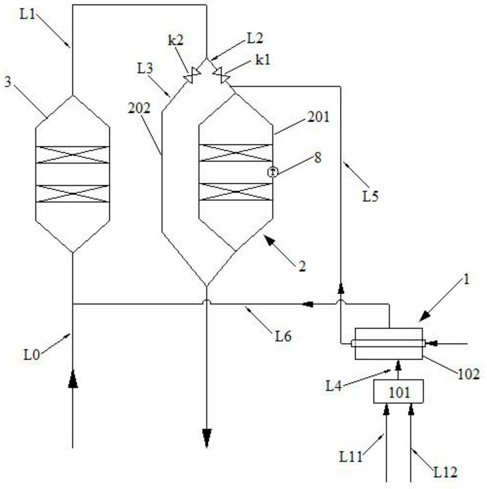
[0104] Such as figure 1 As shown, a heat exchange flue gas denitrification and decarbonization treatment system includes a hot air system 1 , a CO reactor 2 , and an SCR reactor 3 . The hot blast system 1 includes a hot blast stove 101 and a heat exchanger 102 . The CO reactor 2 includes a main reaction tower 201 and a bypass 202 . The original flue gas delivery pipe L0 is connected to the flue gas inlet of the SCR reactor 1, and the first pipe L1 drawn from the flue gas outlet of the SCR reactor 1 is divided into a second pipe L2 and a third pipe L3, and the second pipe L2 and The third pipeline L3 is respectively connected to the main reaction tower 201 and the bypass 202 of the CO reactor 2 . The fourth pipe L4 drawn from the hot blast outlet of the hot blast stove 101 is connected to the first medium inlet of the heat exchanger 102 . A fifth pipe L5 drawn from the second medium outlet of the heat exchanger 102 is connected to the second pipe L2. A second temperature de...

Embodiment 2

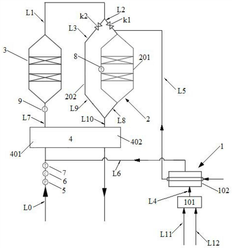
[0106] Example 1 is repeated, except that the first medium outlet of the heat exchanger 102 is connected to the raw flue gas delivery pipeline L0 via the sixth pipeline L6.

Embodiment 3

[0108] Embodiment 2 is repeated, except that the system further includes a first valve k1 arranged on the second pipeline L2. The first valve k1 is located upstream of where the fifth pipeline L5 is connected to the second pipeline L2. The system also includes a second valve k2 arranged on the third line L3. The system also includes a gas delivery pipeline L11 connected to the supplementary gas inlet of the hot blast stove 101 . The system also includes a combustion-supporting gas delivery pipeline L12, which is connected to the supplementary combustion-supporting gas inlet of the hot blast stove 101 .


PUM


Abstract

The invention discloses a heat exchange type flue gas denitration and decarburization treatment system. The system comprises a hot air system (1), a CO reactor (2) and an SCR reactor (3), wherein thehot air system (1) comprises a hot air furnace (101) and a heat exchanger (102); wherein a raw flue gas conveying pipeline (L0) is connected to a flue gas inlet of the SCR reactor (1), a second pipeline (L2) and a third pipeline (L3) are branched from a first pipeline (L1) led out from a flue gas outlet of the SCR reactor (1), and the second pipeline (L2) and the third pipeline (L3) are respectively connected to a main reaction tower (201) and a bypass (202) of the CO reactor (2); a fourth pipeline (L4) led out from a hot air outlet of the hot air furnace (101) is connected to a first medium inlet of the heat exchanger (102); and a fifth pipeline (L5) led out from a second medium outlet of the heat exchanger (102) is connected to the second pipeline (L2). According to the invention, the problem that a CO catalyst is easy to inactivate when meeting sulfur oxide in a low-temperature state is avoided, and meanwhile, the use of fuel is saved.

Description

technical field [0001] The invention relates to a treatment system and a treatment method for flue gas purification, in particular to a heat exchange type flue gas denitrification and decarbonization treatment system and method, belonging to the technical fields of chemical industry and environmental protection. Background technique [0002] For industrial flue gas, especially for sintering machine flue gas in the iron and steel industry, flue gas denitrification technology is a flue gas purification technology applied to the chemical industry where multiple nitrogen oxides are generated. Flue gas denitrification refers to the removal of the generated NO X Revert to N 2 , so as to remove NO from the flue gas X According to the treatment process, it can be divided into wet denitrification and dry denitrification. Flue gas denitrification technologies mainly include dry method (selective catalytic reduction flue gas denitrification, selective non-catalytic reduction method ...

Claims


Application Information

Patent Timeline
IPC IPC(8): B01D53/75B01D53/62B01D53/86B01D53/56
CPCB01D53/75B01D53/62B01D53/8628B01D53/8631B01D2258/0283Y02A50/20
Inventor 叶恒棣魏进超刘昌齐康建刚
Owner ZHONGYE-CHANGTIAN INT ENG CO LTD
Why Eureka
Try Eureka