Flue gas treatment system

A flue gas treatment system and flue gas technology, applied in gas treatment, solid fuel, dispersed particle filtration, etc., to achieve the effect of solving poisoning failure

Pending Publication Date: 2019-01-25
BEIJING ZHONGNENG NUOTAI ENERGY SAVING & ENVIRONMENTAL PROTECTION CO LTD
View PDF9 Cites 1 Cited by
  • Summary
  • Abstract
  • Description
  • Claims
  • Application Information

AI Technical Summary

Problems solved by technology

[0005] In view of this, an embodiment of the present invention provides a flue gas treatment system to solve some or all of the aforementioned problems

Method used


Image

  • Flue gas treatment system
  • Flue gas treatment system
  • Flue gas treatment system

Examples


Embodiment Construction

[0035] In order to enable those skilled in the art to better understand the technical solutions in the embodiments of the present invention, the following will clearly and completely describe the technical solutions in the embodiments of the present invention in conjunction with the accompanying drawings in the embodiments of the present invention. Obviously, the described The embodiments are only some of the embodiments of the present invention, but not all of them. All other embodiments obtained by persons of ordinary skill in the art based on the embodiments in the embodiments of the present invention shall fall within the protection scope of the embodiments of the present invention.

[0036] The specific implementation of the embodiments of the present invention will be further described below in conjunction with the accompanying drawings of the embodiments of the present invention.

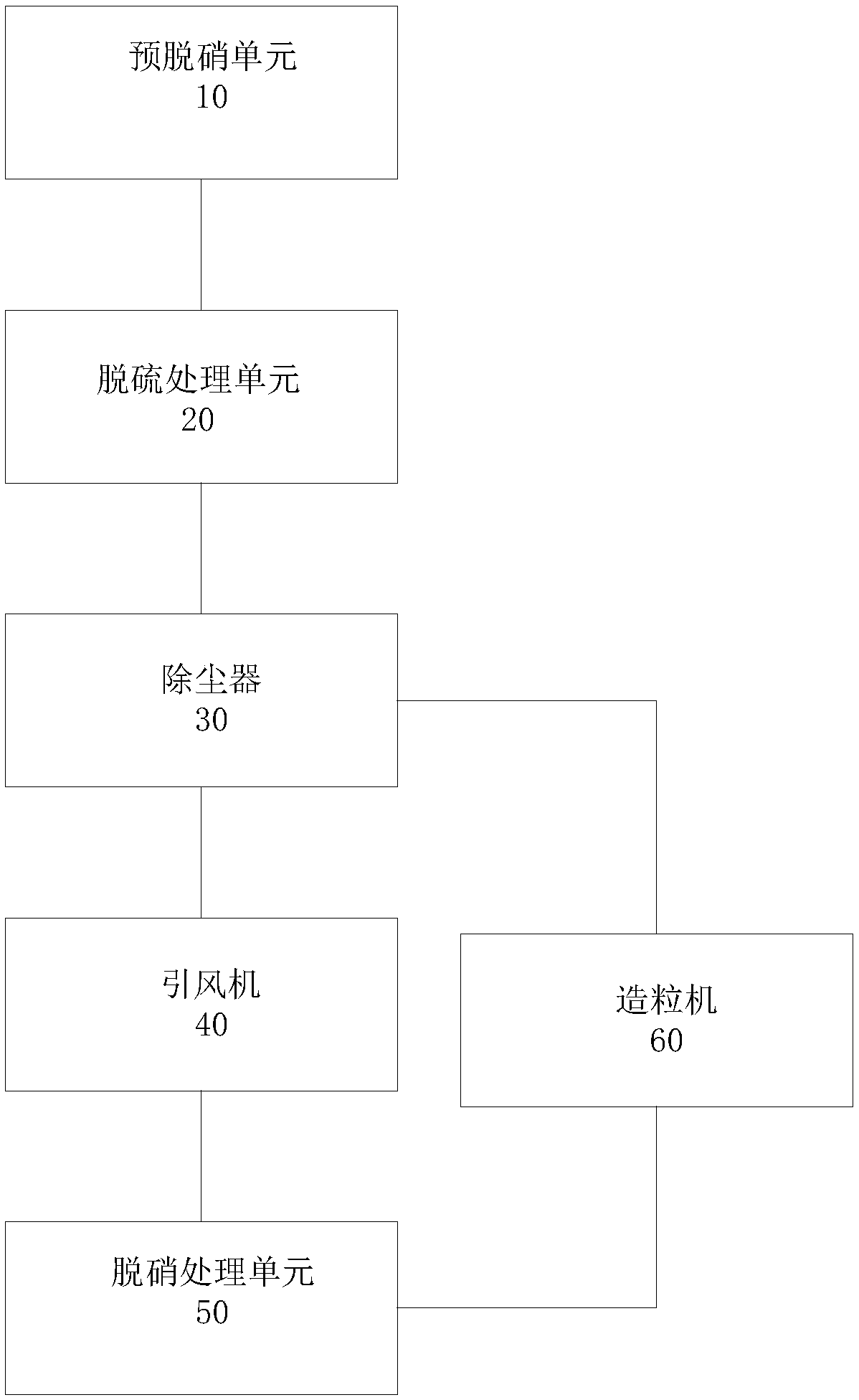
[0037] like figure 1 As shown, according to the embodiment of the present invention, the...


PUM

PropertyMeasurementUnit
diameteraaaaaaaaaa
diameteraaaaaaaaaa

Abstract

The embodiment of the invention provides a flue gas treatment system. The flue gas treatment system comprises a denitration treatment unit, the denitration treatment unit comprises a reaction tower and a sorbent catalytic denitration structure, and the sorbent catalytic denitration structure is disposed in the reaction tower, so that a denitration reducing agent entering the reaction tower and nitrides in to-be-treated flue gas react under the catalysis of the sorbent catalytic denitration structure and undergo denitrification. The flue gas treatment system has a good flue gas treatment effect.

Description

technical field [0001] The embodiments of the present invention relate to the technical field of environmental protection equipment, and in particular to a flue gas treatment system. Background technique [0002] At present, it is the general trend to adopt incineration reduction and energy conversion methods for domestic waste disposal. Garbage incineration can minimize the environmental pollution caused by garbage dumping, and at the same time, it can generate electricity to realize energy regeneration. However, the flue gas produced during the incineration process still contains sulfur dioxide (referred to as sulfur), nitrogen oxides (referred to as nitrate), dust, dioxin and other substances that are still very harmful to the environment, and further treatment of the incineration flue gas is required. Desulfurization and denitrification, etc., to avoid direct emission of flue gas after incineration to harm the environment. [0003] In the prior art, the SCR (selective ...

Claims


Application Information

Patent Timeline
Patent Type & Authority Applications(China)
IPC IPC(8): B01D53/75B01D53/79B01D53/86B01D53/56B01D53/80B01D53/50B01D53/70B01D53/04C10L5/46B01D46/02
CPCB01D46/02B01D53/04B01D53/50B01D53/56B01D53/70B01D53/75C10L5/46B01D2251/2062B01D2253/102B01D2258/0291B01D2257/70B01D2257/302B01D2257/404Y02E50/10Y02E50/30
Inventor 不公告发明人
Owner BEIJING ZHONGNENG NUOTAI ENERGY SAVING & ENVIRONMENTAL PROTECTION CO LTD
Why Eureka
Try Eureka