Cab for construction machine

A technology for engineering machinery and cabs, which is applied in the field of cabs, and can solve problems such as stuffy thighs, sweating of thighs of operators, or feeling hot and uncomfortable, etc.

Pending Publication Date: 2021-02-23
KOBELCO CONSTR MASCH CO LTD
View PDF10 Cites 0 Cited by
  • Summary
  • Abstract
  • Description
  • Claims
  • Application Information

AI Technical Summary

Problems solved by technology

[0003] In addition, when the operator sitting on the driver's seat is working, the thighs that are in contact with the upper surface of the seat will sweat and feel stuffy, which may cause discomfort.
However, the air conditioner described in Patent Document 1 does not take into consideration that the worker's thighs sweat or feel stuffy.

Method used


Image

  • Cab for construction machine
  • Cab for construction machine
  • Cab for construction machine

Examples


Embodiment Construction

[0022] Hereinafter, preferred embodiments of the present invention will be described with reference to the drawings.

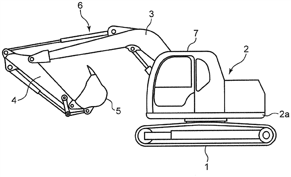
[0023] [Overall structure of construction machinery]

[0024] figure 1 A hydraulic excavator is shown as an example of a construction machine mounted on a cab according to the present invention. This hydraulic excavator includes a crawler-type undercarriage 1 , a slewing upper body 2 mounted thereon, and a working device 6 mounted on the upper slewing body 2 . The upper revolving body 2 has a revolving frame 2a connected to the lower traveling body 1, and a cab 7 mounted on the revolving frame 2a. The working device 6 includes a front end ( figure 1 In the example shown, the boom 3 that is connected to the front end on the right side) to move up and down, the arm 4 that is connected to the distal end of the boom 3 to be rotatable, and the distal end of the arm 4 to be connected to the Rotatable bucket 5.

[0025] The cab 7 is mounted on the front portio...


PUM


Abstract

A cab (7) for a construction machine comprises: a driver's seat (18) having a seat part (18A) and a backrest part (18B); control boxes (20A, 20B) provided to the side of the driver's seat (18); an airconditioner body (31) having a function for cooling air; and a duct (40) that is provided to the rear of the driver's seat (18) and that guides cooling air generated in the air conditioner body (31);discharge ports (41, 42) of the duct (40) being provided to positions such that cooling air flows forward through the side of the seat part (18A) and / or the side of a lower part (18BD) of the backrest part (18B), and also flows forward along inner-side surfaces of the control boxes (20A, 20B).

Description

technical field [0001] The present invention relates to a cab of a construction machine equipped with an air conditioner. Background technique [0002] Conventionally, a cab of a construction machine equipped with an air conditioner is known. For example, the air conditioner described in Patent Document 1 includes a left air outlet provided behind the left rear of the driver's seat, a right air outlet provided behind the right rear of the driver's seat, and a ceiling air outlet provided behind the driver's seat. Patent Document 1 describes that the rear window and the sunroof are covered by an air curtain formed by cold air blown from the air outlet on the roof of the vehicle compartment, and that the left window and the right window are covered by the air curtain formed by the cold air blown from the left air outlet and the right air outlet. curtain overlay. In addition, paragraph [0021] of Patent Document 1 and figure 2 In the described air conditioner, the left air out...

Claims


Application Information

Patent Timeline
Patent Type & Authority Applications(China)
IPC IPC(8): B60H1/34B60H1/00
CPCB60H1/00378B60H1/00564B60H1/00021B60H2001/00185B60H2001/00221B60H2001/00192B60H2001/002E02F9/16B60H1/00285B60H1/34B60Y2200/41
Inventor 藤川幸治太田俊介田代阳平
Owner KOBELCO CONSTR MASCH CO LTD
Why Eureka
Try Eureka