Chamfering equipment for inner circles on two sides and implementation method thereof

A technology of chamfering and equipment, applied in the field of chamfering, can solve the problems of high labor intensity, difficulty in ensuring product production efficiency, and difficult control of chamfering consistency, and achieve the effect of reducing labor intensity, continuous processing, and improving work efficiency

Pending Publication Date: 2021-02-23
东阳东磁自动化科技有限公司
View PDF0 Cites 1 Cited by
  • Summary
  • Abstract
  • Description
  • Claims
  • Application Information

AI Technical Summary

Problems solved by technology

[0003] The existing inner circle chamfering process mainly consists of manual feeding and chamfering, and a small part of it is ground and chamfered by semi-automatic equipment. Since this equipment needs to chamfer both sides of the inner circle of the product, it needs manual loading and unloading many times, labor The strength is high, and the consistency of chamfering is difficult to control, and it is difficult to guarantee the production efficiency of the product

Method used


Image

  • Chamfering equipment for inner circles on two sides and implementation method thereof
  • Chamfering equipment for inner circles on two sides and implementation method thereof
  • Chamfering equipment for inner circles on two sides and implementation method thereof

Examples


Embodiment 1

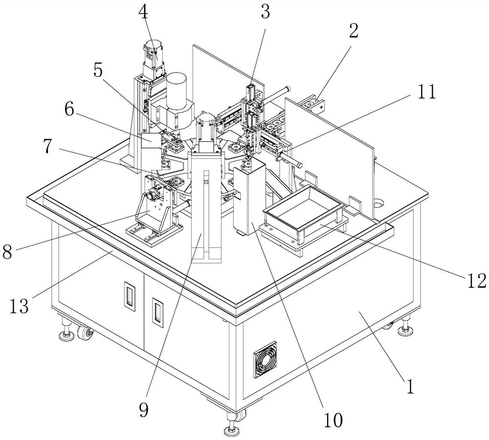
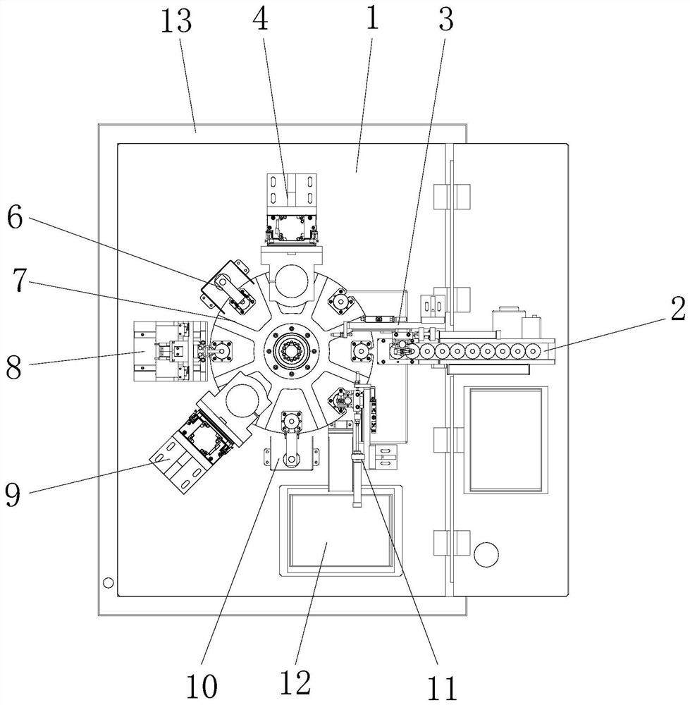
[0051] see Figure 1-9 , the present invention provides the following technical solutions: a double-sided inner circle chamfering equipment, including a frame 1, the middle position above the frame 1 is provided with a rotating platform mechanism 7, and the frame 1 is sequentially provided with a rotating platform mechanism 7 The corresponding suction feeding mechanism 3, the first lifting and chamfering mechanism 4, the first carrier cleaning mechanism 6, the automatic turning mechanism 8, the second lifting and chamfering mechanism 9, the second carrier cleaning mechanism 10 and the suction and unloading mechanism 11, and the top of the frame 1 is provided with a feeding conveyor belt mechanism 2 located below the suction and feeding mechanism 3, and the top of the frame 1 is also provided with a material receiving rubber frame 12 below the suction and unloading mechanism 11, and the feeding and conveying Belt mechanism 2, suction feeding mechanism 3, first lifting and chamf...

Embodiment 2

[0065] The difference between this embodiment and Embodiment 1 is that specifically, the first carrier cleaning mechanism 6 includes a mounting bracket 61, a water shield 62, an air nozzle mounting seat 63 and an air nozzle 64, wherein the mounting bracket 61 is installed on the frame 1, the upper end of the mounting bracket 61 is connected with the air nozzle mounting seat 63, the air nozzle mounting seat 63 is connected with the air nozzle 64, and the outside of the mounting bracket 61 is provided with a water retaining cover 62, and the water retaining cover 62 is installed on the frame 1, a water tank 13 is connected around the frame 1, and the structure of the second carrier cleaning mechanism 10 is the same as that of the first carrier cleaning mechanism 6.

[0066] By adopting the above technical solution, the tool carrier 73 is cleaned by blowing air through the air nozzle 64, the water shield 62 is used to block the blown water mist, and the water tank 13 collects the ...


PUM


Abstract

The invention discloses chamfering equipment for inner circles on two sides and an implementation method thereof, and belongs to the technical field of chamfering. The chamfering equipment comprises arack, a rotating platform mechanism is arranged in the middle of the upper portion of the rack, a sucking and feeding mechanism, a first lifting chamfering mechanism, a first carrier cleaning mechanism, an automatic turnover mechanism, a second lifting chamfering mechanism, a second carrier cleaning mechanism and a sucking and discharging mechanism which correspond to the rotating platform mechanism are sequentially arranged on the rack, a feeding conveying belt mechanism located below the sucking and feeding mechanism is arranged above the rack, and a material collecting rubber frame locatedbelow the sucking and discharging mechanism is further arranged above the rack. The invention further discloses an implementation method of the chamfering equipment for the inner circles on the two sides. According to the chamfering equipment, the first lifting chamfering mechanism, the first carrier cleaning mechanism, the automatic turnover mechanism, the second lifting chamfering mechanism andthe second carrier cleaning mechanism are arranged, so that the two sides of a product are automatically chamfered, the labor intensity of workers is greatly reduced, and the working efficiency of product chamfering is improved.

Description

technical field [0001] The invention belongs to the technical field of chamfering, and in particular relates to a double-sided inner circle chamfering device and a realization method thereof. Background technique [0002] There is an existing product that requires chamfering on both sides of the inner circle, in order to better cover the electroplating layer on the surface of the product. [0003] The existing inner circle chamfering process mainly consists of manual feeding and chamfering, and a small part of it is ground and chamfered by semi-automatic equipment. Since this equipment needs to chamfer both sides of the inner circle of the product, it needs manual loading and unloading many times, labor The strength is high, and the consistency of chamfering is difficult to control, and it is difficult to guarantee the production efficiency of the product. [0004] Therefore, there is an urgent need for a double-sided inner circle chamfering equipment. By providing an autom...

Claims


Application Information

Patent Timeline
IPC IPC(8): B24B27/00B24B9/00B24B41/00B24B41/06B24B55/06B24B41/02B24B47/04B08B5/02
CPCB08B5/02B24B9/00B24B27/0023B24B27/0069B24B41/005B24B41/02B24B41/06B24B47/04B24B55/06
Inventor 邵建伟刘晋胡意周
Owner 东阳东磁自动化科技有限公司
Why Eureka
Try Eureka