
Air energy water heater system and control method

An air-energy water heater and hot water circulation technology, which is applied to fluid heaters, heat pumps, refrigerators, etc., can solve the problems of inability to save energy, keep the temperature unchanged, and damage the compressor, etc., to reduce the exhaust temperature, The effect of reducing overheating loss and large energy saving potential

Inactive Publication Date: 2021-02-19
NINGBO LINESHOW ELECTRIC CO LTD
View PDF7 Cites 0 Cited by
  • Summary
  • Abstract
  • Description
  • Claims
  • Application Information

AI Technical Summary

Problems solved by technology

[0003] However, the current air-energy water heaters mainly use a single-stage vapor compression cycle. Because the temperature that can be absorbed in the air contains sensible heat and latent heat as the ambient temperature and humidity change, sensible heat can make people have obvious changes in cold and heat. Feeling; latent heat means that in the process of an object absorbing or releasing heat, its phase state has changed (such as a gas into a liquid), but the temperature does not change. This absorbed or released heat is called "latent heat", and through a single-stage steam The compression cycle generally adjusts the working speed of the compressor according to the ambient temperature. If the temperature is low, the working speed will be fast; Energy-saving effect

Method used


Image

  • Air energy water heater system and control method
  • Air energy water heater system and control method
  • Air energy water heater system and control method

Examples


Embodiment 1

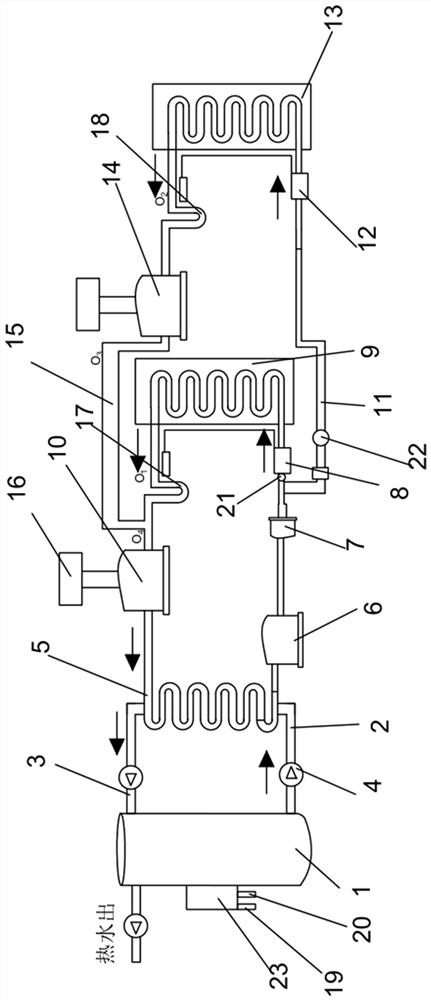
[0027] Such as figure 1 As shown, an air energy water heater system provided in this embodiment includes a low-temperature water tank 1, on which a cold water pipeline 2 and a hot water circulation pipeline 3 are arranged, and between the cold water pipeline 2 and the hot water circulation pipeline 3 A condenser 5 is connected through a circulation pump 4, and a liquid storage tank 6, a filter 7, a first expansion valve 8, and a high-temperature evaporator are sequentially connected in circulation between the refrigerant output end of the condenser 5 and the refrigerant input end of the condenser 5. device 9 and high-pressure compressor 10, a second expansion valve 12 is connected through a first branch pipe 11 on the common connection pipeline between the filter 7 and the first expansion valve 8, and the output of the second expansion valve 12 is connected with a low-temperature An evaporator 13 , the output of the low-temperature evaporator 13 is connected to a low-pressure ...

Embodiment 2

[0035] Such as figure 2 As shown, the general structure of an air energy water heater system provided by this embodiment is the same as that of Embodiment 1, the difference is that it also includes a first temperature sensor 19 and a humidity detection sensor 20 for detecting the ambient temperature. A third temperature sensor 21 is connected to the pipeline connecting the valve 8 and the filter 7, a second temperature sensor 22 is connected to the first branch pipe 11, the first temperature sensor 19, the humidity detection sensor 20, the third temperature sensor Both the sensor 21 and the second temperature sensor 22 are connected to an external controller 23, and the controller 23 can be connected to the first expansion valve 8 and the second expansion valve 12 to control the second expansion valve 12 and the first expansion valve 8 The degree of opening and closing, the controller 23 can be connected with the fan on the high temperature evaporator 9 and the low temperatur...

Embodiment 3

[0041] Such as image 3 As shown, the general structure of an air-energy water heater system provided in this embodiment is the same as that of Embodiment 1, but in this embodiment, below the low-pressure compressor 14 and the high-pressure compressor 10, there are devices for cooling the compressors. The air-cooling device 24, by adding the air-cooling device 24, when it is detected that the temperature of the compressor is too high, the corresponding air-cooling device 24 can be turned on for temporary rapid air-cooling and cooling.


PUM


Abstract

The invention discloses an air energy water heater system. The air energy water heater system comprises a low-temperature water tank, wherein a cold water pipeline and a hot water circulating pipelineare arranged on the low-temperature water tank; a condenser is connected between the cold water pipeline and the hot water circulating pipeline through a circulating pump; a liquid storage tank, a filter, a first expansion valve, a high-temperature evaporator and a high-pressure compressor are sequentially and circularly connected between a refrigerant output end of the condenser and a refrigerant input end of the condenser; a second expansion valve is connected to a common connecting pipeline of the filter and the first expansion valve through a first branch pipe; the output end of the second expansion valve is connected to a low-temperature evaporator; the output end of the low-temperature evaporator is connected to a low-pressure compressor; and the output end of the low-pressure compressor is connected to a common connecting pipeline of the high-temperature evaporator and the high-pressure compressor through a second branch pipe. The invention further discloses a control method ofthe air energy water heater system. Energy-saving effect is improved.

Description

technical field [0001] The invention relates to the technical field of air energy water heater control, in particular to an air energy water heater system and a control method. Background technique [0002] With the development of my country's economy and the improvement of people's living standards, people have more and more requirements for the living environment. While improving the indoor water temperature, air energy water heaters have also greatly increased energy consumption. As we all know, an air energy water heater is composed of a compressor, a water tank, a throttling device and an evaporator, and a condenser is arranged in the water tank. The air energy water heater uses the working principle of the heat pump. The heat exchange medium absorbs the low-energy heat in the air in the evaporator, and is compressed into a high-temperature gas by the compressor. The water in the water tank is heated through the pipeline circulation system. The air-energy water heater ...

Claims


Application Information

Patent Timeline
Patent Type & Authority Applications(China)
IPC IPC(8): F24H4/02F24H9/12F24H9/20F24H9/18F25B30/06F25B41/31F25B41/40F25B43/00
CPCF24H4/02F24H9/2007F24H9/1809F25B30/06F25B43/003F24H9/13
Inventor 董少壮应森杰顾蔚彪郑一琨徐少平
Owner NINGBO LINESHOW ELECTRIC CO LTD
Learn More