Adjustable optical instrument supporting device

A technology of optical instruments and supporting devices, which is applied in the direction of transmission devices, supporting machines, machine platforms/supports, etc., can solve the problems of difficult and inconvenient adjustment of optical instruments and optical instruments, and achieve accurate rotation, easy operation, and adjustment and placement height effect

Inactive Publication Date: 2021-02-19
九江宇昆光学科技有限公司
View PDF9 Cites 4 Cited by
  • Summary
  • Abstract
  • Description
  • Claims
  • Application Information

AI Technical Summary

Problems solved by technology

[0005] In order to overcome the shortcomings in the prior art that it is inconvenient for people to adjust the direction of the optical instrument, and it is difficult to adjust the height of the optical instrument to a large extent, the technical problem to be solved is: to provide a method that can adjust the rotation direction of the optical instrument, and can adjust the height of the optical instrument to a large extent. Adjustable Optical Instrument Support Device for Placement of Optical Instruments

Method used


Image

  • Adjustable optical instrument supporting device
  • Adjustable optical instrument supporting device
  • Adjustable optical instrument supporting device

Examples


Embodiment 1

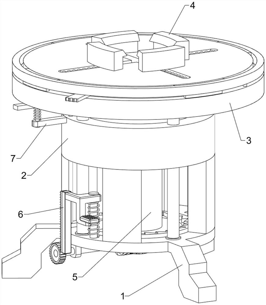
[0031] An adjustable optical instrument support device, such as figure 1 and figure 2 As shown, it includes a support foot 1, a support frame 2, a rotating assembly 3 and a fixed assembly 4, the top of the support foot 1 is fixedly connected to the support frame 2, the top of the support frame 2 is provided with a rotating assembly 3, and the rotating assembly 3 is connected to a fixed assembly 4.

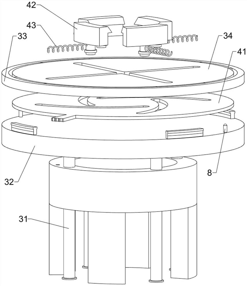
[0032] The rotating assembly 3 includes a first guide rod 31, a first support plate 32, a slide rail 33 and a first turntable 34. Four first guide rods 31 are evenly spaced on the top of the support foot 1, and the first guide rods 31 pass through the support A first support plate 32 is installed between the frame 2 and the top of the first guide rod 31 , a slide rail 33 is slidably installed on the top of the first support plate 32 , and a first turntable 34 is connected to the inside of the slide rail 33 .

[0033] The fixed assembly 4 includes a second turntable 41, a slider ...

Embodiment 2

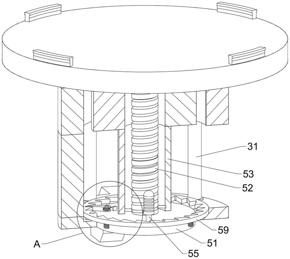
[0036]On the basis of Example 1, such as image 3 , Figure 4 , Figure 5 , Figure 6 , Figure 7 , Figure 8 , Figure 9 and Figure 10 As shown, it also includes a rising assembly 5, and the rising assembly 5 includes a third turntable 51, a first worm 52, a second support plate 53, a first connecting rod 54, a handle 55, a pawl 56, a torsion spring 57, a second Two guide rods 58, the first ratchet 59 and the second spring 510, the middle part of the support foot 1 is rotatably provided with the third turntable 51, the middle part of the third turntable 51 is connected with the first worm 52, and the middle part of the first support plate 32 bottom is connected with the first turntable. Two support plates 53, the second support plate 53 is located on the outside of the first worm 52, the inner side of the second support plate 53 is symmetrically connected with the first connecting rod 54, and the first connecting rod 54 is matched with the first worm 52, and the third ...


PUM


Abstract

The invention relates to a supporting device, in particular to an adjustable optical instrument supporting device. The technical problem to be solved is to provide the adjustable optical instrument supporting device capable of adjusting the rotation direction of an optical instrument and greatly adjusting the placement height of the optical instrument. The adjustable optical instrument support device comprises support legs connected with a supporting frame, a rotating assembly arranged at the top of the supporting frame, and a fixing assembly connected to the rotating assembly. The effects that the rotating direction of the optical instrument can be adjusted, and the placement height of the optical instrument can be greatly adjusted are achieved. The optical instrument can be clamped on afirst rotating disc through sliding blocks and first springs, so that the optical instrument is not prone to moving, and the optical instrument can be prevented from being damaged.

Description

technical field [0001] The invention relates to a support device, in particular to an adjustable optical instrument support device. Background technique [0002] Optical instruments are mainly used in the optical field. Common optical instruments include spectrometers, biological microscopes and magnifying glass lamps. People often use these optical instruments when doing experiments. Because optical instruments are usually relatively expensive, People need to use it carefully to prevent it from being broken. [0003] The existing optical instrument support seat, such as the Chinese patent with the patent notification number CN204901250U, discloses an optical instrument support seat, which includes a support surface and a support rod, the support rod is located at the center of the support surface, and several connecting rods are arranged at the bottom of the support surface , the connecting rod is connected to the bottom of the supporting surface through threads, and the s...

Claims


Application Information

Patent Timeline
Patent Type & Authority Applications(China)
IPC IPC(8): F16M11/04F16M11/08F16M11/30F16M11/42F16M7/00F16H37/12
CPCF16M11/041F16M11/08F16M11/30F16M11/42F16M7/00F16H37/124
Inventor 李炎
Owner 九江宇昆光学科技有限公司
Why Eureka
Try Eureka