Multi-shaft spraying device for coating preparation
A spraying device and coating technology, which is applied in the direction of spraying devices, liquid spraying devices, etc., can solve the problems of inability to spray irregular objects, low melt-blown coverage, poor spraying integrity, etc., to achieve better covering effect, convenient spraying, Spray for full effect
- Summary
- Abstract
- Description
- Claims
- Application Information
AI Technical Summary
Problems solved by technology
Method used
Image

Examples
Embodiment 1
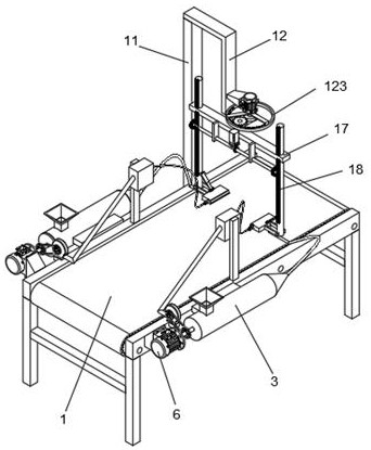
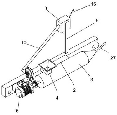
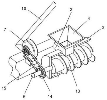
[0038] Such as Figure 1-Figure 3 As shown, a multi-axis spraying device for coating preparation includes a conveyor belt 1, and the left end of the conveyor belt 1 has a front and rear symmetrical structure and is fixed with two fixed blocks 2, and a round tube 3 is fixed on the outside of the fixed block 2, and the round tube 3 The top surface of the left end is fixed with a feed hopper 4, the middle part of the left wall of the feed hopper 4 is sleeved with a rotating shaft 5, the left end of the rotating shaft 5 is coaxially connected with a motor A6, the left end of the fixed block 2 is provided with a blower 7, and the top surface of the middle part of the conveyor belt 1 is front and rear. The symmetrical structure is fixed with two support blocks 8, the inner wall of the upper end of the support block 8 is fixed with a heater 9, the air outlet end of the blower 7 is connected with an air outlet pipe 10, and the upper right corner of the conveyor belt 1 is fixed with a v...
Embodiment 2
[0043] Such as Figure 4-Figure 6 As shown, on the basis of Embodiment 1, the right end of the Z-shaped rod 12 is provided with a rotating rod 121, the rotating rod 121 is sleeved with a half gear 122, the upper end of the half gear 122 is provided with a rotating ring 123, and the upper end of the rotating rod 121 is provided with The motor B124, the inner wall of the left end of the rotating ring 123 is embedded with an arc-shaped ring gear 125, the arc-shaped ring gear 125 is meshed with a gear A126, and the middle part of the gear A126 is sleeved with a round rod 127.
[0044] The rotating rod 121 is connected with the Z-shaped rod 12 in rotation, the half gear 122 and the rotating ring 123 are connected and fixed with the rotating rod 121, the half gear 122 is meshed with the gear A126, and the motor B124 is installed on the right wall of the middle part of the Z-shaped rod 12 through the mount. The output shaft of the motor B124 is coaxially connected with the rotating r...
Embodiment 3
[0050] Such as Figure 7 As shown, on the basis of Embodiment 2, the lower end of the positioning rod 18 is provided with a melt-blown assembly 26, and the melt-blown assembly 26 includes a melt-blown die head 261, and the inner end of the melt-blown die head 261 is arranged with two hot air The pipe 262 and the outer wall of the melt-blown die head 261 have a left-right symmetrical structure and are fixed with two connecting rods 263. The upper side of the melt-blown die head 261 is provided with an electric push rod 264, and the upper and lower ends of the electric push rod 264 are rotatably connected with hinge seats 265. .
[0051] The hot air pipe 262 is connected with the Y-shaped hose 16, the middle part of the outer wall of the melt-blown die head 261 is connected with the extrusion hose 27, the outer end of the connecting rod 263 is rotationally connected with the lower end of the positioning rod 18, and the hinge seat 265 at the upper end is connected with the positi...
PUM
 Abstract
Description
Claims
Application Information
 - Generate Ideas
- Intellectual Property
- Life Sciences
- Materials
- Tech Scout
- Unparalleled Data Quality
- Higher Quality Content
- 60% Fewer Hallucinations
Browse by: Latest US Patents, China's latest patents, Technical Efficacy Thesaurus, Application Domain, Technology Topic, Popular Technical Reports.
© 2025 PatSnap. All rights reserved.Legal|Privacy policy|Modern Slavery Act Transparency Statement|Sitemap|About US| Contact US: help@patsnap.com