Anti-seismic prefabricated beam-column joint of fabricated building and construction method of anti-seismic prefabricated beam-column joint
A technology of beam-column joints and prefabricated beams, which is applied in the direction of protective buildings/shelters, buildings, building components, etc., can solve the problems of cumbersome construction process, high cost, and low construction efficiency, and achieve good earthquake resistance and assembly efficiency High, the effect of improving the seismic performance
- Summary
- Abstract
- Description
- Claims
- Application Information
AI Technical Summary
Problems solved by technology
Method used
Image
Examples
specific Embodiment 1
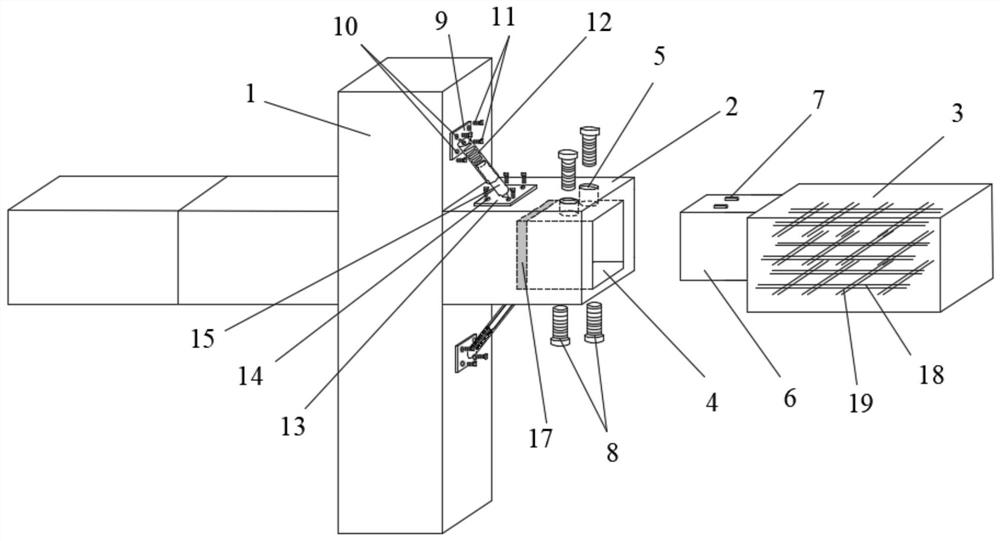
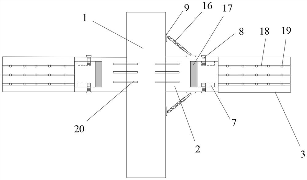
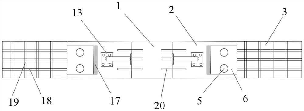
[0028] figure 1 It is a schematic diagram of the overall structure of the anti-seismic prefabricated beam-column joints of the prefabricated building of the present invention. and combine Figures 2 to 4 It can be seen that the anti-seismic prefabricated beam-column node of the prefabricated building of the present invention includes a prefabricated column 1, a first prefabricated beam 2, a second prefabricated beam 3 and a connector 20, one end of the connector 20 is located in the prefabricated column 1, and the other end Located in the first prefabricated beam 2, fix the prefabricated column 1 and the first prefabricated beam 2, the connector 20 is perpendicular to the prefabricated column 1 and parallel to the first prefabricated beam 2; The fixing plates A9 are arranged in pairs on the two side walls of the prefabricated column 1 and the first prefabricated beam 2, and the fixing plates A9 on any side wall are respectively arranged above and below the first prefabricated...
specific Embodiment 2
[0030] The construction method of the seismic prefabricated beam-column joint of the prefabricated building includes the following steps:
[0031] Step S1: making prefabricated columns 1, first prefabricated beams 2, second prefabricated beams 3, connectors 20, fixing plates A9 and fixing plates B13 in the factory;
[0032] Step S2: Fix one end of the connector 20 in the prefabricated column 1, and fix the other end of the connector 20 in the first prefabricated beam 2;
[0033] Step S3: Sleeve the rotating sleeve 12 on the fixed plate A9 onto the rotating sleeve rod 15 of the fixed plate B13, and fix the upper and lower sides of the first prefabricated beam 2 on both sides of the prefabricated column 1 through toothed bolts B11 The fixing plate A9 is used to respectively fix the fixing plate B13 on the upper surface and the lower surface of the first prefabricated beam 2 through toothed bolts B11;
[0034] Step S4: A buffer gap 17 is formed between the groove 4 of the first ...
PUM
 Abstract
Description
Claims
Application Information
 - R&D
- Intellectual Property
- Life Sciences
- Materials
- Tech Scout
- Unparalleled Data Quality
- Higher Quality Content
- 60% Fewer Hallucinations
Browse by: Latest US Patents, China's latest patents, Technical Efficacy Thesaurus, Application Domain, Technology Topic, Popular Technical Reports.
© 2025 PatSnap. All rights reserved.Legal|Privacy policy|Modern Slavery Act Transparency Statement|Sitemap|About US| Contact US: help@patsnap.com


