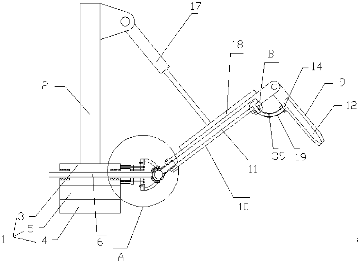
A luffing type hard pipe filling device applied in bad sea conditions
A filling device and sea state technology, which is applied in distribution devices, special distribution devices, liquid distribution, transportation or transfer devices, etc., can solve the problems that it is difficult to apply ship filling, and cannot meet the six degrees of freedom displacement of ships, so as to reduce the horizontal Impact force, improve filling efficiency, improve filling safety effect
Active Publication Date: 2019-11-19
ZHEJIANG OCEAN UNIV
View PDF2 Cites 0 Cited by
- Summary
- Abstract
- Description
- Claims
- Application Information
AI Technical Summary
Problems solved by technology
Method used
View moreImage
Smart ImageViewing Examples
Examples
Embodiment Construction
[0033] In order to make the technical solution of the present invention clearer, the present invention will be further described below in conjunction with the accompanying drawings. Any solution obtained by equivalent replacement and conventional reasoning of the technical features of the technical solution of the present invention falls within the protection scope of the present invention.
Login to View More PUM
 Abstract
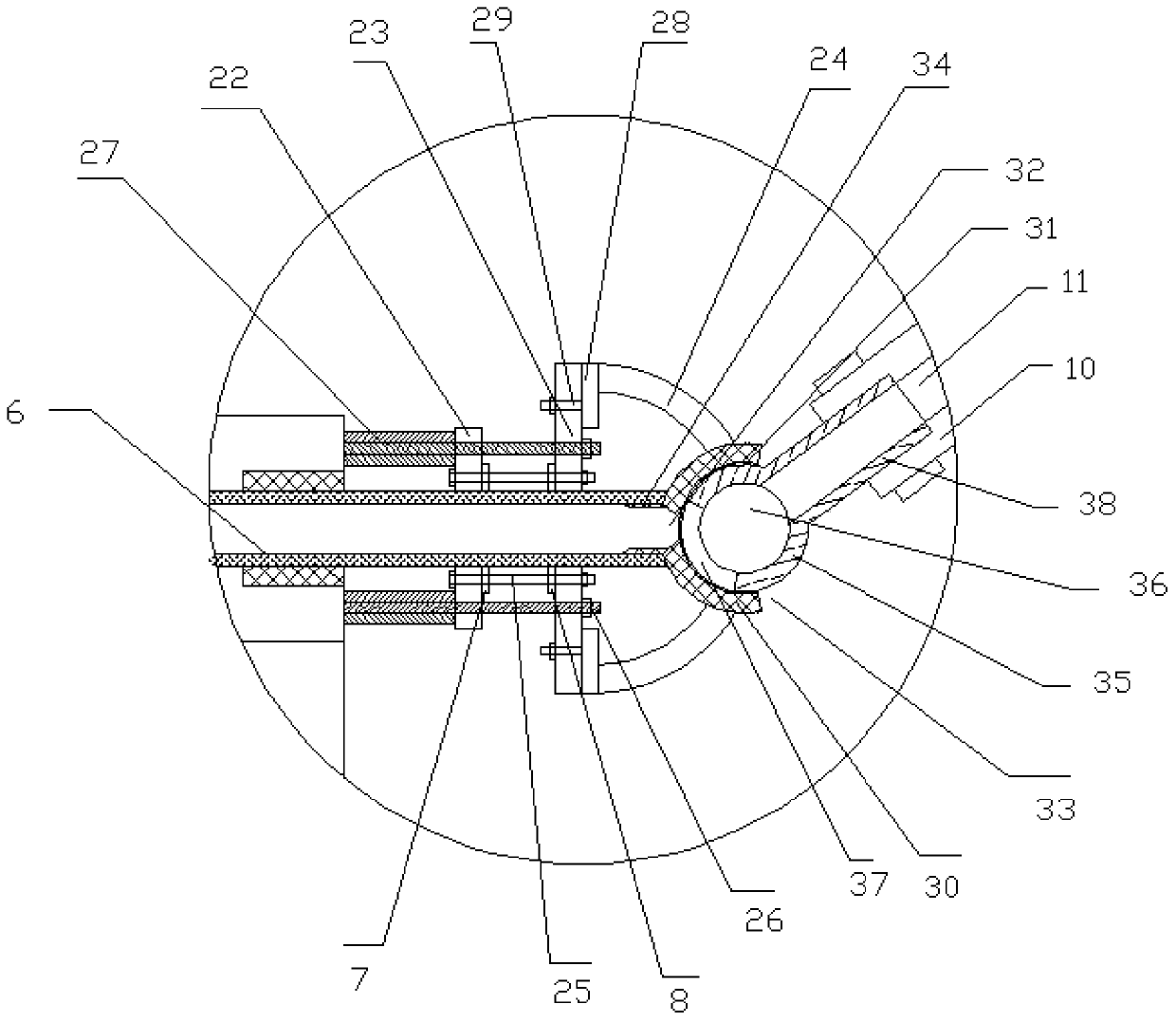
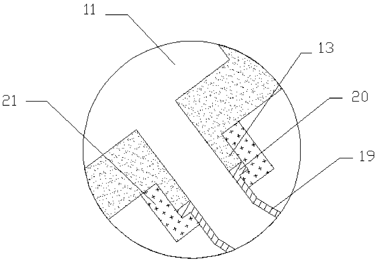
The invention provides a variable-amplitude hard tube filling device applied to poor sea conditions. The device comprises a base, a stand column and a filling arm assembly, wherein a filling pipelineis horizontally arranged on the base, the filling arm assembly comprises an outer filling arm and an inner filling arm, a first channel is formed in the outer filling arm, and a second channel is arranged on the inner filling arm; a first switching tube is arranged on the side wall of the top of the first channel, a second switching tube is arranged on the side wall of the top of the second channel, the first switching tube and the second switching tube are connected through a first switching assembly, and the inner filling arm is connected with the filling pipeline through a second switchingassembly; the top of the stand column is rotationally and fixedly provided with a hydraulic cylinder through a second rotating shaft, a sliding block is rotationally arranged on a push rod of the hydraulic cylinder, and the sliding block is movably arranged on a sliding rail; and the sliding rail is fixed to the inner filling arm. The filling device is reasonable in design, and the filling efficiency and the filling safety are improved.
Description
technical field [0001] The invention relates to a filling device, in particular to a luffing type hard pipe filling device applied in bad sea conditions. Background technique [0002] In today's marine fueling process of ships, the fueling method is mostly used to fuel the fuel through the hose by means of the side. The filling process is greatly restricted by factors such as the filling method and the filling arm. At the same time, when the drop of the ship is large, the hose will wear out during the filling process and cause fuel leakage, which poses a serious safety hazard. In addition, the conventional soft Pipe filling greatly affects the filling speed and affects the filling efficiency. This traditional hose filling method cannot be applied to ship fuel filling under complex sea conditions. [0003] Patent CN 201711193235.7 discloses a marine fuel filling device and control method, including a tether launch device, an oil tank, an abutment, a rotating arm on the abut...
Claims
Login to View More Application Information
Patent Timeline
 Patent Type & Authority Patents(China)
IPC IPC(8): B67D7/42B67D7/36
CPCB67D7/36B67D7/42
Inventor 王德东汪世林王栋博
Owner ZHEJIANG OCEAN UNIV
Features
- Generate Ideas
- Intellectual Property
- Life Sciences
- Materials
- Tech Scout
- Unparalleled Data Quality
- Higher Quality Content
- 60% Fewer Hallucinations
Learn More Browse by: Latest US Patents, China's latest patents, Technical Efficacy Thesaurus, Application Domain, Technology Topic, Popular Technical Reports.
© 2025 PatSnap. All rights reserved.Legal|Privacy policy|Modern Slavery Act Transparency Statement|Sitemap|About US| Contact US: help@patsnap.com


