Ecological slope protection maintenance system
A maintenance system and ecological slope protection technology, applied in coastline protection, excavation, watering devices, etc., can solve the problems of high labor intensity of ecological slope protection maintenance workers, and achieve the effects of increasing the irrigation range, fast start-up speed, and environmental protection
- Summary
- Abstract
- Description
- Claims
- Application Information
AI Technical Summary
Problems solved by technology
Method used
Image
Examples
Embodiment 1
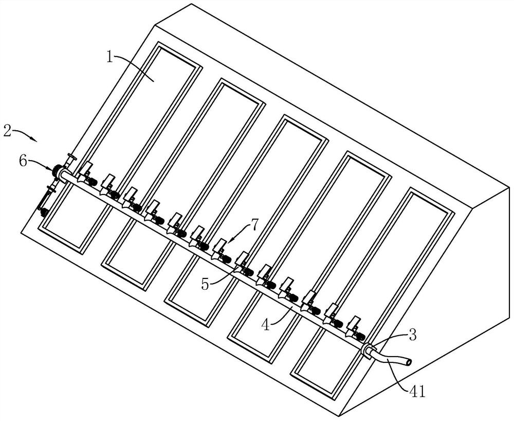
[0037] Such as figure 1 As shown, the ecological slope protection maintenance system includes a slope protection body 1 and an irrigation device 2. Vegetation is planted on the slope of the slope protection body 1, and the irrigation device 2 is arranged on the slope of the slope protection body 1 to reciprocate and water the vegetation in a large area.
[0038] The irrigation device 2 includes a support frame 3, a main pipe 4, a pouring part 5, and an adjustment mechanism 6, wherein the frame body of the support frame 3 is spliced by several support plates and support rods, and the support frame 3 can be fixed on the slope by buried bolts. On the surface, it provides the installation foundation for the main pipeline 4 and the adjustment mechanism 6 .
[0039] The main pipe 4 is horizontally rotated and installed on the support frame 3. One end of the main pipe 4 is closed and the other end is open. Connect to provide irrigation water source for the main pipeline 4.
[004...
Embodiment 2
[0047] Such as image 3 , Figure 4 As shown, the difference between this embodiment and Embodiment 1 lies in that a sprinkler assembly 7 for suppressing the water flow is provided on the pouring member 5 .
[0048] The water diffuser assembly 7 comprises a support 71, a water diffuser plate 72, a power member 73, a crank 74 and a rocker 75, wherein the support 71 is fixedly installed on the auxiliary pipe 51, and the top of the support 71 is provided with a groove downward, and the water diffuser plate 72 Located in the groove, it is installed on the support 71 through the horizontal rotation of the rotating shaft; the axis of the rotating shaft is perpendicular to the axis of the auxiliary pipe 51 . The end of the water-spreading plate 72 facing the input end of the secondary pipeline 51 is set as a connection end, and the end of the water-sprinkling plate 72 facing the output end of the secondary pipeline 51 is set as a water-spraying end.
[0049] The power part 73, the ...
Embodiment 3
[0053] Such as Figure 5 As shown, the difference between this embodiment and Embodiment 2 is that the power member 73 is driven by water pressure.
[0054] The power element 73 includes a rotating shaft 731 and an impeller 732. The rotating shaft 731 is partly penetrated in the auxiliary pipe 51, and is connected to the pipe wall of the auxiliary pipe 51 in a sealed rotation; the impeller 732 is coaxially installed on the transmission shaft located in the auxiliary pipe 51. The crank 74 is affixed to the end of the transmission shaft outside the auxiliary pipeline 51 , and the rocking bar 75 is eccentrically hinged on the crank 74 .
[0055] When the irrigation water flows through the auxiliary pipeline 51, it can automatically drive the impeller 732 to rotate, and the impeller 732 then synchronously drives the rotation shaft 731 to rotate, and the reciprocating swing power structure starts to work, driving the water distribution plate 72 to reciprocate periodically to increa...
PUM
 Abstract
Description
Claims
Application Information
 - R&D
- Intellectual Property
- Life Sciences
- Materials
- Tech Scout
- Unparalleled Data Quality
- Higher Quality Content
- 60% Fewer Hallucinations
Browse by: Latest US Patents, China's latest patents, Technical Efficacy Thesaurus, Application Domain, Technology Topic, Popular Technical Reports.
© 2025 PatSnap. All rights reserved.Legal|Privacy policy|Modern Slavery Act Transparency Statement|Sitemap|About US| Contact US: help@patsnap.com


