Automobile charging pile

A technology of car charging and charging piles, which is applied in the direction of electric vehicle charging technology, charging stations, electric vehicles, etc., and can solve the inconvenient use of car charging piles, the inability to monitor the environment of car charging piles, and the inability to move, retrieve and store car charging piles, etc. question

Inactive Publication Date: 2021-02-19
李福友
View PDF19 Cites 1 Cited by
  • Summary
  • Abstract
  • Description
  • Claims
  • Application Information

AI Technical Summary

Problems solved by technology

[0003] The existing car charging piles have certain disadvantages when they are used. They cannot monitor the environment around the car charging piles. It is inconvenient for maintenance personnel to understand the use of the car charging piles. They cannot be moved, recovered and stored, and charging cannot be guaranteed. Safety of Pile Storage Outside

Method used


Image

  • Automobile charging pile
  • Automobile charging pile
  • Automobile charging pile

Examples


Embodiment 1

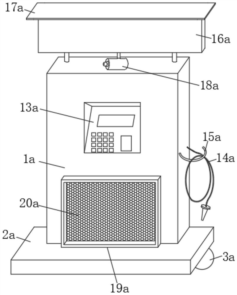
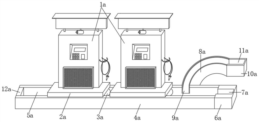
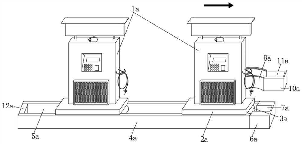
[0043]SeeFigure 1-7 This embodiment provides a technical solution: an automobile charging pile, including a charging pile body 1a and a linear slide 4a, the top of the charging pile body 1a is fixedly connected with a moisture-proof seat 2a, and the bottom of the moisture-proof seat 2a is fixedly installed with a rail The number of wheels 3a and rail wheels 3a is two. The two rail wheels 3a are symmetrically arranged at the bottom of the moisture-proof seat 2a. The top of the linear slide 4a is provided with a linear groove 5a, and the rail wheel 3a is movably connected in the linear groove 5a, One side of the linear slide rail 4a is fixedly connected with a first positioning seat 6a, and a side of the first positioning seat 6a close to the linear slide rail 4a is provided with a first fitting groove 7a, and the first fitting groove 7a is in communication with the linear groove 5a , The right end of the rear side of the linear slide rail 4a is fixedly connected with an arc rail 8a, ...

Embodiment 2

[0053]On the basis of the first embodiment above, this embodiment also provides an automobile charging pile with a lighting system;

[0054]CombineFigure 1 to Figure 19As shown, the car charging pile includes a charging pile body 1a, a linear slide 4a and a lamp post 1. The top of the charging pile body 1a is fixedly connected with a moisture-proof seat 2a, and the bottom of the moisture-proof seat 2a is fixedly installed with a rail wheel 3a. The number of 3a is two. The two rail wheels 3a are symmetrically arranged at the bottom of the moisture-proof seat 2a. The top of the linear slide rail 4a is provided with a linear groove 5a, and the rail wheel 3a is movably connected in the linear groove 5a. One side is fixedly connected with a first positioning seat 6a, and a first fitting groove 7a is formed on the side of the first positioning seat 6a close to the linear slide rail 4a. The first fitting groove 7a communicates with the linear groove 5a, and the linear slide rail 4a The right ...


PUM


Abstract

A disclosed automobile charging pile comprises a charging pile body and a linear sliding rail, a damp-proof base is fixedly connected to the top of the charging pile body, a rail wheel is fixedly installed at the bottom of the damp-proof base, a linear groove is formed in the top of the linear sliding rail, and the rail wheel is movably connected into the linear groove; and a first setting seat isfixedly connected to one side of the linear sliding rail, a first matching groove is formed in the side, close to the linear sliding rail, of the first setting seat, the first matching groove communicates with the linear groove, an arc-shaped rail is fixedly connected to the right end of the rear side of the linear sliding rail, and an arc-shaped groove is formed in the arc-shaped rail. Accordingto the automobile charging pile, when the charging pile body is used, the charging pile body can swing anticlockwise, so that the charging pile body is converted into a using state from a retractingstate and can move on the linear sliding rail, multiple charging pile bodies can be retracted on the setting base, and the charging pile bodies are placed in order through the first matching groove and a second matching groove, so that the charging pile bodies are cleaner and tidier.

Description

Technical field[0001]The invention relates to the technical field of automobile charging piles, in particular to an automobile charging pile.Background technique[0002]The function of the car charging pile is similar to the refueling machine. It can be installed in the parking lot or charging station of public buildings and residential quarters, and can charge various types of electric vehicles according to different voltage levels. Charging piles generally provide both conventional charging and fast charging. Kind of charging method.[0003]Existing car charging piles have certain drawbacks when in use. They cannot monitor the environment around the car charging piles, and it is not convenient for maintenance personnel to understand the usage of the car charging piles. The car charging piles cannot be moved, retracted and stored, and charging cannot be guaranteed. The safety of piles stored outside.[0004]Therefore, it is necessary to design a car charging pile to solve the above-menti...

Claims


Application Information

Patent Timeline
IPC IPC(8): B60L53/31B60L53/30B60L53/302B60L53/60B60L53/66
CPCB60L53/31B60L53/30B60L53/302B60L53/60B60L53/665Y02T10/70Y02T10/7072Y02T90/12Y02T90/16
Inventor 李福友
Owner 李福友
Why Eureka
Try Eureka