
Injection mold with ejection mechanism

A technology of injection mold and ejection mechanism, which is applied in the field of molds, can solve the problems of friction between the mold and the inner wall of the mould, easy friction damage during demoulding, and difficult demoulding, so as to achieve accurate positioning, stable bottom mold, and reduce the actual The effect of using space

Inactive Publication Date: 2021-02-19
孟燕飞
View PDF6 Cites 0 Cited by
  • Summary
  • Abstract
  • Description
  • Claims
  • Application Information

AI Technical Summary

Problems solved by technology

Injection molds in the prior art have the problem that it is not easy to demould and easy to be damaged by friction during demoulding, because some molds have molds on the inner wall. The use of ejector pins will cause friction between the mold and the inner wall of the mold when the mold is ejected, resulting in frictional damage to the mold

Method used


Image

  • Injection mold with ejection mechanism
  • Injection mold with ejection mechanism
  • Injection mold with ejection mechanism

Examples


Embodiment Construction

[0028] The following will clearly and completely describe the technical solutions in the embodiments of the present invention with reference to the accompanying drawings in the embodiments of the present invention. Obviously, the described embodiments are only some, not all, embodiments of the present invention.

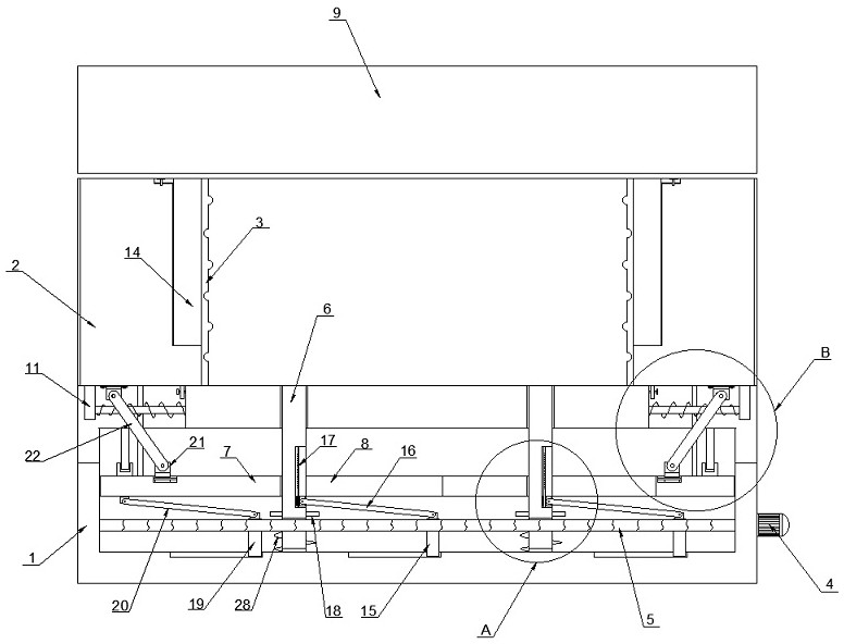
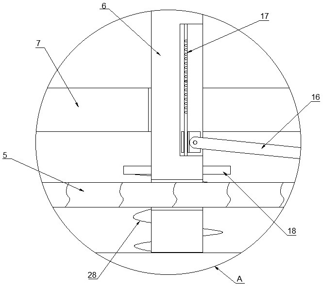
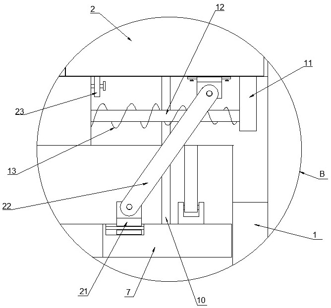
[0029] refer to Figure 1-5 , an injection mold with an ejection mechanism, including a base 1, the outer wall of the base 1 is connected with four partitions 2 through a connecting mechanism,

[0030] Further, the connecting mechanism includes a connecting plate 11 fixed on the bottom of the partition plate 2, the connecting plate 11 is fixedly connected with the insertion rod 12, the outer wall of the base 1 is provided with a slot corresponding to the insertion rod 12, and the insertion rod 12 The outer wall is covered with a first spring 13, and the two ends of the first spring 13 are respectively fixedly connected with the outer wall of the base 1 and the outer ...


PUM


Abstract

The invention discloses an injection mold with an ejection mechanism. The injection mold with the ejection mechanism comprises a base, four partition plates are connected to the outer side wall of thebase through connecting mechanisms, mold plates are connected to the partition plates, and a bottom mold is formed by the four partition plates with the mold plates; and a mounting cavity is formed in the base, a rotating motor is fixedly connected to the outer side wall of the base, a threaded rod is fixedly connected to the output end of the rotating motor, and a plurality of ejector pins are connected to the threaded rod through a first adjusting mechanism. The mold is reasonable in structural design, by arranging third adjusting mechanisms, the multiple partition plates can be driven to move outwards at the same time when a sliding plate moves upwards, horizontal separation between the mold and the mold plates can be achieved, the mold demolding problem that a model arranged on the inner side wall of the mold is not likely to machine can be solved, and secondly, by adopting the demolding method, damage caused by friction between the machined mold and the bottom mold can be avoided.

Description

technical field [0001] The invention relates to the technical field of molds, in particular to an injection mold with an ejection mechanism. Background technique [0002] Mold, various molds and tools used in industrial production for injection molding, blow molding, extrusion, die-casting or forging, smelting, stamping, etc. Formed in the mold. The injection molds in the prior art have the problem that it is not easy to demould and easy to be damaged by friction when demoulding, because some molds have molds on the inner wall, and if a thimble is used to straighten the mold, the mold after injection will be damaged. The straight ejection of the thimble will cause friction between the mold and the inner side wall of the mold when the mold is ejected, resulting in frictional damage to the mold. Contents of the invention [0003] The object of the present invention is to propose an injection mold with an ejection mechanism in order to solve the problems existing in the pri...

Claims


Application Information

Patent Timeline
IPC IPC(8): B29C45/26B29C45/40
CPCB29C45/2602B29C45/2673B29C45/4005B29C45/401B29C2045/4021
Inventor 孟燕飞
Owner 孟燕飞
Learn More