
A kind of on-chip integrated optical microcavity coupling structure and preparation method

A technology of optical microcavity and integrated optics, applied in the field of optical devices, to solve the problem of mechanical stability and easy to prepare

Active Publication Date: 2022-03-18
NANJING UNIV
View PDF0 Cites 0 Cited by
  • Summary
  • Abstract
  • Description
  • Claims
  • Application Information

AI Technical Summary

Problems solved by technology

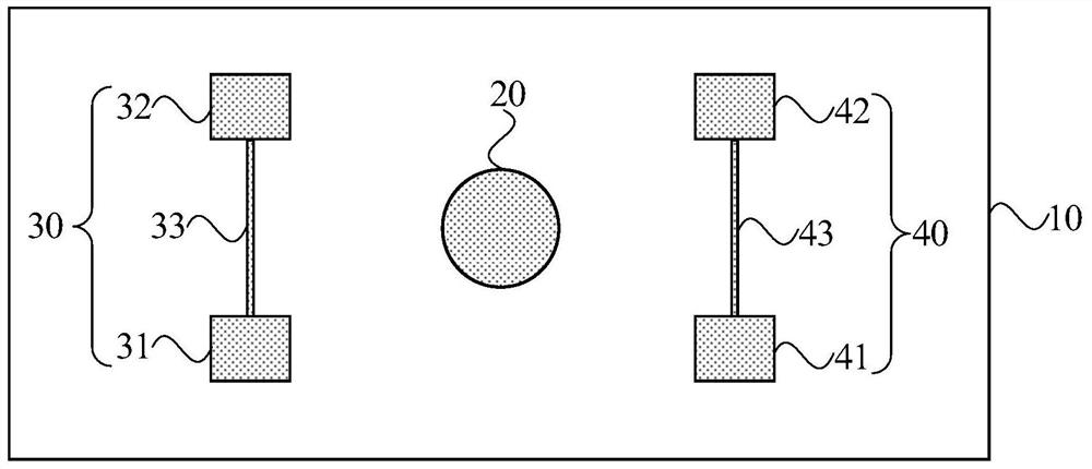
[0005] The embodiment of the present invention provides an on-chip integrated optical microcavity coupling structure and preparation method, so that the relative position of the tapered optical fiber and the optical microcavity remains stable, thereby solving the mechanical stability problem necessary for long-term measurement in the experiment, and The preparation process of this structure is completely compatible with the preparation process of the existing optical microcavity, easy to prepare, and can provide a packaging idea to solve the mechanical stability for the future industrialization of the optical microcavity

Method used


Image

  • A kind of on-chip integrated optical microcavity coupling structure and preparation method
  • A kind of on-chip integrated optical microcavity coupling structure and preparation method
  • A kind of on-chip integrated optical microcavity coupling structure and preparation method

Examples


Embodiment Construction

[0046] The present invention will be further described in detail below in conjunction with the accompanying drawings and embodiments. It should be understood that the specific embodiments described here are only used to explain the present invention, but not to limit the present invention. In addition, it should be noted that, for the convenience of description, only some structures related to the present invention are shown in the drawings but not all structures.

[0047] Terms used in the embodiments of the present invention are only for the purpose of describing specific embodiments, and are not intended to limit the present invention. It should be noted that the orientation words such as "up", "down", "left", and "right" described in the embodiments of the present invention are described from the angles shown in the drawings, and should not be interpreted as a reference to the implementation of the present invention. Example limitations. Also in this context, it also nee...


PUM

PropertyMeasurementUnit
diameteraaaaaaaaaa

Abstract

The embodiment of the invention discloses an on-chip integrated optical microcavity coupling structure and a preparation method. The coupling structure includes a substrate; an optical microcavity disposed on the substrate, a first cantilever beam and a second cantilever beam; the first cantilever beam includes a first support body, a second support body and a first cantilever beam, and the second cantilever beam includes The third support body, the fourth support body and the second cantilever, the optical microcavity is located between the first cantilever and the second cantilever; the first cantilever and the second cantilever are used to support the tapered optical fiber and the optical microcavity coupling both ends of the fiber. The technical scheme of the embodiment of the present invention keeps the relative position of the tapered optical fiber and the optical microcavity stable, thereby solving the problem of mechanical stability necessary for long-term measurement in the experiment, and the preparation process of the structure is different from that of the existing optical microcavity The preparation process is fully compatible and easy to prepare, which can provide a packaging idea to solve the mechanical stability for the future industrialization of optical microcavities.

Description

technical field [0001] Embodiments of the present invention relate to optical device technology, in particular to an on-chip integrated optical microcavity coupling structure and a preparation method. Background technique [0002] On-chip ultra-high quality factor silicon dioxide whispering gallery mode optical microcavity samples were prepared for the first time in 2003. This optical microcavity has the advantages of high Q value, low loss, and small mode volume, so it is a good experimental The platform is widely used by researchers in various projects. [0003] In order to effectively inject laser light into this whispering gallery mode optical microcavity, common coupling methods include prism coupling, fiber end face coupling, and tapered fiber coupling. Among them, tapered fiber coupling is the most commonly used by researchers, because its coupling efficiency can easily be higher than 90%, and the process of preparing tapered fiber is relatively simple and convenient...

Claims


Application Information

Patent Timeline
Patent Type & Authority Patents(China)
IPC IPC(8): G02B6/293G02B6/122G02B6/138
CPCG02B6/29341G02B6/122G02B6/138G02B2006/12147
Inventor 姜校顺拜子琦
Owner NANJING UNIV
Learn More