
Automatic comprehensive testing machine

A technology of comprehensive testing and testing institutions, applied in circuit breaker testing, testing of mechanical components, testing of machine/structural components, etc., can solve problems such as time-consuming, labor-intensive, and low degree of automation

Pending Publication Date: 2021-02-12
深圳市达鑫自动化有限公司
View PDF0 Cites 1 Cited by
  • Summary
  • Abstract
  • Description
  • Claims
  • Application Information

AI Technical Summary

Problems solved by technology

[0002] At present, during the production process of the relay, it needs to go through the pull-in test, IP / OP high-voltage test (that is, the high-voltage test between the coil and the contact of the relay), and the OP / OP high-voltage test (that is, the contact between the contact and the contact of the relay). High voltage test), electric washing test and comprehensive function test. The existing relay test equipment is usually an independent device, which requires manual operation of the relevant test equipment to test the above tests separately. The operation is complicated and cannot be performed sequentially on one device. To complete all tests, the manual labor intensity is high, time-consuming and labor-intensive, the degree of automation is low, and the test efficiency is low

Method used


Image

  • Automatic comprehensive testing machine
  • Automatic comprehensive testing machine
  • Automatic comprehensive testing machine

Examples


Embodiment Construction

[0051] The present invention will be further described in detail below in conjunction with the accompanying drawings and embodiments. It should be understood that the specific embodiments described here are only used to explain the present invention, but not to limit the present invention. In addition, it should be noted that, for the convenience of description, only some structures related to the present invention are shown in the drawings but not all structures.

[0052]In the description of the present invention, unless otherwise clearly specified and limited, the terms "connected", "connected" and "fixed" should be understood in a broad sense, for example, it can be a fixed connection, a detachable connection, or an integrated ; It can be a mechanical connection or an electrical connection; it can be a direct connection or an indirect connection through an intermediary, and it can be the internal communication of two components or the interaction relationship between two c...


PUM


Abstract

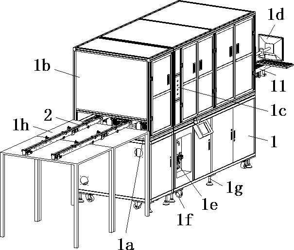
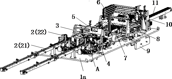
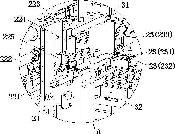
The invention discloses an automatic comprehensive testing machine which comprises a rack provided with a workbench, a feeding mechanism, a caching and transferring mechanism, a first conveying mechanism, a first grabbing mechanism, an attraction testing mechanism, a second conveying mechanism, a second grabbing mechanism, a four-in-one testing mechanism, a third grabbing mechanism and a discharging mechanism. The feeding mechanism, the caching and transferring mechanism, the first conveying mechanism, the attraction testing mechanism, the second conveying mechanism and the discharging mechanism are sequentially arranged on the workbench from front to back, the first grabbing mechanism is arranged on the workbench above the first conveying mechanism, and the second grabbing mechanism is arranged on the workbench above the second conveying mechanism; and the four-in-one testing mechanism is arranged on the workbench behind the second grabbing mechanism, and the third grabbing mechanismis arranged on the workbench above the discharging mechanism. Five kinds of tests can be sequentially completed on the same equipment, full-automatic testing is achieved, manual labor is effectively reduced, time and labor are saved, and the testing efficiency is improved.

Description

technical field [0001] The invention relates to the technical field of automatic testing equipment, in particular to an automatic comprehensive testing machine. Background technique [0002] At present, during the production process of the relay, it needs to go through the pull-in test, IP / OP high-voltage test (that is, the high-voltage test between the coil and the contact of the relay), and the OP / OP high-voltage test (that is, the contact between the contact and the contact of the relay). High voltage test), electric washing test and comprehensive function test. The existing relay test equipment is usually an independent device, which requires manual operation of the relevant test equipment to test the above tests separately. The operation is complicated and cannot be performed sequentially on one device. To complete all the tests, the manual labor intensity is high, time-consuming and laborious, the degree of automation is low, and the test efficiency is low. [0003] T...

Claims


Application Information

Patent Timeline
Patent Type & Authority Applications(China)
IPC IPC(8): G01R31/327G01R31/01G01M13/00B65G43/08B65G47/90B65G47/82B65G47/91B65G47/52B65G47/24
CPCG01R31/3278G01R31/01G01M13/00B65G43/08B65G47/901B65G47/82B65G47/912B65G47/52B65G47/24B65G2203/042Y02P90/02
Inventor 庞发权罗敏彭海峰
Owner 深圳市达鑫自动化有限公司
Learn More